scottie3158
SMF Supporter
Colin,
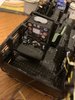
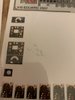
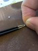
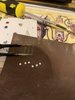
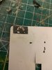
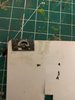
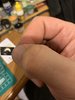
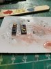
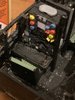
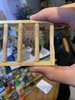
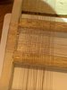
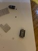
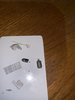
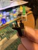
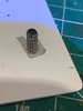
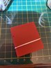
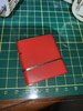
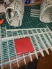
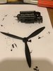
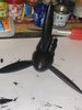
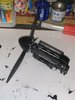
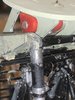
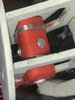
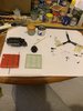
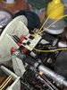
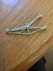
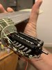
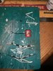
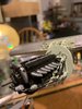
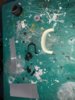
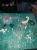
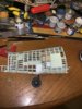
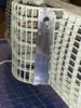
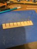
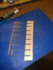
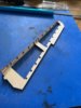
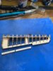
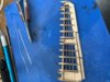
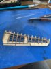
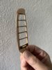
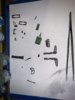
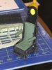
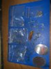
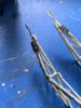
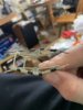
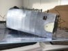
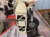
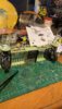
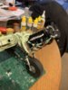
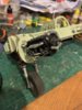
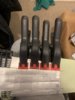
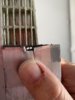
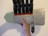
Some great looking details.
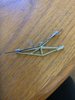
Some great looking details.


For FULL Forum access you can upgrade your account here UPGRADE