US Army M32B1 Tank Recovery Vehicle

Jakko

Way past the mad part
SMF Supporter
Joined
Apr 28, 2018
Messages
10,773
Points
113
First Name
Jakko
What I find kind of odd is that the US Army called the M32’s turret, well, “turret” despite the fact that it couldn’t rotate. On a tank-like vehicle, “turret” conjures up a picture of a rotating one, but I guess it’s a throwback to the original meaning of the word here :smiling3:
 

Jakko

Way past the mad part
SMF Supporter
Joined
Apr 28, 2018
Messages
10,773
Points
113
First Name
Jakko
Looking for something I could use to line up the hubs and the discs, I eventually found this:
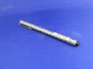
A16E9A0F-7D6B-43AA-BFBD-84164FBB0AE3.jpeg

The black end of this draughting pen fits well in the hole in the hub:
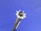
5D21D153-5867-4C49-9420-1E20C7D3C85A.jpeg

… allowing me to glue the disc to it neatly as well:
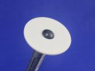
10DA8327-9A78-4CD9-805C-EF9409C8B6E9.jpeg

Do that eighteen times, leave to dry and do the other side (lining up the spokes by eye) and you have:
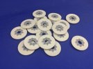
B3905758-5F6B-4202-8AA5-195A3B21E168.jpeg

Another task tackled. Until you dry-fit things and find that:
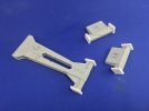
990355A8-1517-48AE-85AF-FE9D1959EA56.jpeg

… a set of six discs is too wide to fit the Bold Division parts :sad: I first thought I might be able to sand down the hubs a little, but the set of six discs is about 4 mm too wide, meaning 1/3 mm has to come off each hub. But the ring on each is only 0.3 mm thick, so that’s a no-go …

I then looked at, and measured in, a drawing in Steve Zaloga’s old Military Modelling article in which he builds this combination in 1:76 scale, and I found that the Bold Division arms are about 2 mm too narrow, altogether. That means that adding another millimetre on each side isn’t that big a deal, so I glued 2 mm plastic card to both sides, after sawing off the square locating pen that was there.

When the glue had dried, I cut them to roughly match the set’s parts:
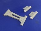
60969A5E-0F45-4417-A694-42E383E0F91E.jpeg

I still need to file these down to be seamless, but it was getting too hot in my modelling room :smiling3:
 
Last edited:

Jim R

SMF Supporter
Joined
Apr 27, 2018
Messages
13,711
Points
113
Location
Shropshire
First Name
Jim
Just shows that your kind of modelling is actually 50% problem solving. You're certainly getting there.
Jim
 

Jakko

Way past the mad part
SMF Supporter
Joined
Apr 28, 2018
Messages
10,773
Points
113
First Name
Jakko
Thanks :smiling3: Though one of these days, I would like to build a model that just assembles out of the box without needing any additional work to correct problems … :smiling3:
 

Jakko

Way past the mad part
SMF Supporter
Joined
Apr 28, 2018
Messages
10,773
Points
113
First Name
Jakko
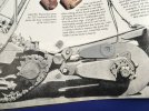
Well, this is fun … Now the heat is over, I thought I’d continue building the mine roller. I had already discovered that the Bold Division instructions don’t really tell you at which height to fit the beam at the front of the tank to which the rollers attach, but I found a photo that shows it really well in an article by Steve Zaloga in Military Modelling. With that in hand, I found the kit parts simply can’t fit the way the real thing did :sad: Either it sits at the right height but with an edge at the top instead of a flat, or it sits far too low with a flat side at the top.

It turns out the support is entirely wrong, as you can see here (the support is on the drive sprocket, not that obvious):

3C68B51C-0D90-4BEE-B174-9139B9841B28.jpeg

And that’s not all, which is why the other parts are on there too. The brackets into which the roller parts hinge, are wrong too: the one at the top should sit on a flat, but Bold Division gives you one that sits on both sides of the edge, while at the bottom, it’s the other way around (I didn’t mix them up: you get two for the top and four for the bottom). And then there’s the large side plate for the rollers: the lid on that has clearly the wrong shape and the wrong pattern of bolts on it … less obviously, it’s also missing the bevel along its outer edge.

This will give me a good deal of extra work to make new brackets after figuring out their shapes, and to correct those bolted lids and bevelled edges :sad:
 

Jim R

SMF Supporter
Joined
Apr 27, 2018
Messages
13,711
Points
113
Location
Shropshire
First Name
Jim
It's one thing after another with this build. I have no doubt you'll sort it and it does make for an interesting blog.
 

Jakko

Way past the mad part
SMF Supporter
Joined
Apr 28, 2018
Messages
10,773
Points
113
First Name
Jakko
It’s par for the course for these kinds of models I build, it seems. I think I said before I would really like to build something straight from the box one of these days, though :smiling3:
 

Jakko

Way past the mad part
SMF Supporter
Joined
Apr 28, 2018
Messages
10,773
Points
113
First Name
Jakko
That thought had occurred to me too: a lot of people would probably just build the thing per the instructions and be quite happy with the result :smiling3:
 

Scratchbuilder

SMF Supporter
Joined
Jul 2, 2022
Messages
1,918
Points
113
First Name
Mike
Jakko,
Just caught up with your build, and a lot of building is going on. I agree with you on the problems with resin kits, and the fit and warping. But you will overcome as usual. Great work.
Mike.
 

Jakko

Way past the mad part
SMF Supporter
Joined
Apr 28, 2018
Messages
10,773
Points
113
First Name
Jakko
Thanks :smiling3: This is all correctible, definitely, just a lot more work than I expected so it’s a bit of a setback when I kind of want to get this model finished sooner rather than later. The main problem I now see is figuring out the shape of the supports between the tank and the hexagonal beam, everything else is easy enough to measure and estimate from the picture above but the actual shape of the supports is very hard to make out.
 
Top