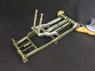
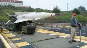
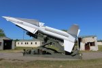
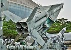
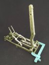
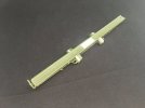
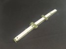
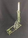
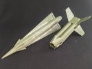
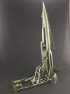
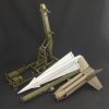
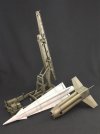
1:35 MIM-14 Nike Hercules

Jakko

Way past the mad part
SMF Supporter
Joined
Apr 28, 2018
Messages
10,797
Points
113
First Name
Jakko
As mentioned elsewhere, I bought the Nike Hercules kit by Freedom Model Kits just under a week ago, thinking it would be a good model to put together at the model show I spent the weekend at.

Right …

First impression is that it’s quite a decent kit. Maybe not quite up to the latest standards, but it looks pretty good on the sprues. I started building the launcher, on the basis that would give me somewhere to put the missile, rather than do it in the order the kit’s instructions tell you to: missile first, launcher second. In the end, I doubt it matters much, really, because what you will soon find out is that the initial appearance is a little deceiving.

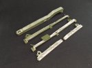
This kit is from 2019, and I think I said it before, but it bears repeating: it feels like it’s from the 1980s. If you’ve built a couple of Italeri kits, this one will feel so familiar it makes you wonder whether Freedom Models reissued an old Italeri kit from 30 or 40 years ago — but Italeri never had a Nike Hercules, so they must have tooled it new like this. Parts fit is reasonable but you don’t get nearly enough locating pins and tabs, and most parts need fettling either before or after gluing them together. And a good deal of filler for any major parts. I mean, take a look at this:
IMG_0805.jpeg

It would probably have been better to add some plastic strip inside some of these parts to raise the inserts to the proper height, reducing the need for filler, but I was at a model show and didn’t have any at hand. The large part at the top (the arm that raises the missile to launch position) didn’t need much filler but did need a lot of filing to get rid of the raised seam between the two parts.

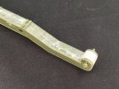
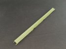
Or this, the launch rail:
IMG_0798.jpeg

That’s two parts, with a huge, low-lying seam top and bottom all around. That’ll be fun to fill, because the raised lips along the sides need to stay. I might just file those off and replace them by plastic strip, though, to make it easier to fill the seam.

Much of the above is caused by the parts being slightly angled to get them out of the mould, by the way. This causes the join between the parts to either be lower or higher than the outside edges. The rest is due to very loose fit, sometimes in combination with the previous.

Also, the mould seams (rather than seams between parts) are very obvious as well. Those on the launcher parts almost all needed a good deal of filing to get the sides of the parts flat.

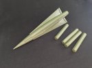
Oddly, the main parts for the missile body and the four booster rockets fit much better:
IMG_0795.jpeg

They still needed a seam removed, of course, but nowhere near as bad as on the launcher. After glueing, I lined the halves up as well as I could, and then filed and sanded down the seams when the glue was dry. That just left rescribing some panel lines on the missile, but nothing major.

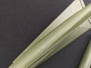
And then you fit the main wings:
IMG_0796.jpeg

These are difficult to align correctly because their locating tabs are far too shallow, but more importantly, they leave a big gap all along those tabs …

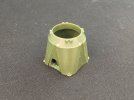
The piece that connects the boosters to the missile also has some large gaps:
IMG_0797.jpeg

This is ten parts! Bottom plate, top ring, four rounded bits at the corners, and four triangular ones to go between them. It’s difficult to line everything up correctly because once again, few locating pins and very little positive fit. On the plus side, once it’s dry you can use it as a stand for the missile, so you don’t have to rest it on its wings while the glue on those dries :smiling3:

Oh, and for anyone after details on the real thing: https://ed-thelen.org/ — when you look past his political, philosophical and other misguided beliefs, this is a treasure trove of Nike Hercules material, including what looks like a complete set of technical manuals.
 
Last edited:

Jim R

SMF Supporter
Joined
Apr 27, 2018
Messages
13,726
Points
113
Location
Shropshire
First Name
Jim
Looks rather a challenge Jakko. I suppose if it's the only game in town then you have to deal with it. Time consuming but nothing you can't handle.
 

Jakko

Way past the mad part
SMF Supporter
Joined
Apr 28, 2018
Messages
10,797
Points
113
First Name
Jakko
True, I think. It requires slightly above basic modelling skills, but nothing an average modeller can’t handle, IMHO. However, I realised tonight, when trying to get the lower frame of the launcher square, that this is most definitely not a kit for one kind of person it is likely to appeal to: ex-Nike crewmen … They won’t care about the seams, probably, but if a reasonably experienced modeller like yours truly is struggling to get the base square, they never will …
 

Jakko

Way past the mad part
SMF Supporter
Joined
Apr 28, 2018
Messages
10,797
Points
113
First Name
Jakko
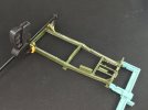
How I got the chassis reasonably square:

IMG_0807.jpeg

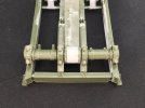
The rear crossbeam (at the large, black clamp on the left) is still loose, but the others are glued in place. Without the two clamps, it’s just about impossible to even keep the parts together, because if you pull them together at the front, they’ll part at the back and vice versa. Even with the clamps on, the whole thing was skewed to the right (the front side being angled towards the camera), so I had to line up the rear beam and feet with one of the lines on my cutting mat and then push and pull, with quite some force, to get the feet on the side to line up with a perpendicular line.

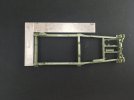
Even then, it’s only just about square:

IMG_0808.jpeg

The above is after the glued dried overnight, BTW.

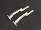
The two main elevating arms are probably the worst part in this kit:

IMG_0810.jpeg

Each of these is two pieces, glued together lengthwise and leaving a big seam like I’ve mentioned a few times now :smiling3: I filled them with putty, filed and sanded that smooth, and found I could still see and feel the seam line. So, a second round of putty, filing and sanding, and still a visible seam line. The next step was a coat of Mr. Surfacer, to make it clearer where there were still lower-lying areas, followed by more putty in the deeper areas — deliberately thick enough that it wouldn’t shrink into them — and then a third round of filing and sanding. At this point, I don’t care anymore if there may still be lower areas, this is how I’ll leave it :smiling3:

Just for kicks, here’s another shot of a typical part as you find it on the sprues:

IMG_0814.jpeg

Look at the size of those mould lines. That is not what I’d expect of a 2020s kit.

I then assembled then elevating mechanism, but found that to line it up correctly, I needed to fit it into the chassis:

IMG_0815.jpeg

This was tricky too, because not only is the glue on the elevating arms still wet, I had to try and get the shorter longitudinal beams in between the middle and rear crossbeams without everything going flying. Again, it needs the clamp for things to stay together, which doesn’t bode well for when I glue these parts (there is no more glue on the chassis than in the previous picture of it: only the main elevating arms and their crosspieces have been glued here).
 

minitnkr

Rabble & escape committee member
SMF Supporter
Joined
Apr 27, 2018
Messages
6,717
Points
113
Location
Dayton, OH
First Name
Paul
A real monster. Reminds me of some resin kits I've had the misfortune to encounter.
 

Jakko

Way past the mad part
SMF Supporter
Joined
Apr 28, 2018
Messages
10,797
Points
113
First Name
Jakko
I don’t think I’d want to build this in resin :smiling3: On the other hand, things would have been moulded in far fewer parts that way, so less to try and line up correctly.

TBH, it’s mainly the design of this kit that makes it difficult. Take those elevating arms: they’re moulded in two pieces, an inner and an outer, and then need a full-height crossbeam (two more pieces with a seam) glued between them, and that beam needs filing flat all around the locating pegs before it will sit correctly. Had they moulded the elevating arms in top and bottom parts, with the left and right arms plus crossbeam as a single piece, it would all have been much more solid. Of course, that puts the big, V-shaped join on the sides, where there is detail, so maybe flat top and bottom pieces, both H-shaped (elevating arms and main crossbar) with separate parts for the sides of the arms — with solid enough locating lugs that they will simply fit at right angles only — would work.

Anyway, IMHO this kit has no insurmountable problems, but it suffers from poor design and outdated moulding, which make it much trickier to assemble than it needed to have been.

And here’s a thought: AFV Club announced a 1:35 scale Nike Hercules kit as well, but that was in 2020 and it stills shows as “Future” on Scalemates. Though that also says “New tool”, I’m beginning to wonder if maybe they intended to rebox this one from Freedom Model Kits (they’re both Taiwanese) but thought the better of it once they tried building one? No idea if I’m right, but it seems at least plausible …
 

Jim R

SMF Supporter
Joined
Apr 27, 2018
Messages
13,726
Points
113
Location
Shropshire
First Name
Jim
A challenge for sure. Spending time ensuring the chassis is square should lessen issues later on as you build onto it. Those mould lines are horrendous. You could certainly understand if AFV Club were indeed "frightened off".
 

Jakko

Way past the mad part
SMF Supporter
Joined
Apr 28, 2018
Messages
10,797
Points
113
First Name
Jakko
I’ve by now decided to mostly build it straight from the box, adding just a bit of detail where it’s very obviously missing, or when it needs to be replaced due to filling gaps etc. Still wondering how best to tackle the launch rail, though …
 

yak face

Wossupwidee?
Staff member
Moderator
SMF Supporter
Joined
Jun 13, 2009
Messages
12,400
Points
113
Location
sheffield
First Name
tony
Great reference pics there paul , should be very useful for jakkos launch rail
 

Jakko

Way past the mad part
SMF Supporter
Joined
Apr 28, 2018
Messages
10,797
Points
113
First Name
Jakko
Just in case you didn't have any refs.
I hadn’t seen those, but then, I hadn’t really looked ;) The South Korean camouflage is interesting, and the kit provides markings and a painting guide for it. Not sure yet which I’ll go for — probably either that, or a Dutch missile in white and OD.

Great reference pics there paul , should be very useful for jakkos launch rail
They are, mainly in that they show you can’t see much of the rail’s top surface :smiling3: I was thinking about that this morning, and decided that the best thing to do will be to put the missile on it so I can see how much of the launch rail will actually be visible, and thus, how much needs to be filled. The underside will need much more filling than the top, by the looks of it, but still, it means I’ll probably have to do a lot less filling than I expected.
 

Jakko

Way past the mad part
SMF Supporter
Joined
Apr 28, 2018
Messages
10,797
Points
113
First Name
Jakko
Thanks :smiling3: As I mentioned earlier, I’ve found Ed Thelen’s site when looking for information, and it seems to have everything you care to know about Nike Hercules and more.

Another example of this kit’s poor design: there are some removable lids on the launcher erecting beam (the big, central arm in the launcher, on which the launch rail sits), but rather than mould openings in the beam and give the covers as separate bits, they’re moulded as part of the beam halves. That means there’s a big seam running down the middle and they don’t have the bolt heads that hold them on IRL. Using some of the references on that site, I filed off the cover on the curved lower end of the launcher and replaced it with thin plastic card (simpler than trying to fill a big seam on a curved section) and then added bolt heads around it from 0.5 mm punched discs:

IMG_0816.jpeg

You can’t see them on the plastic card because of over-exposure, but they’re there :smiling3:

Next, I assembled all of the major parts of the launcher. Look at how well the back fits:

IMG_0819.jpeg

Again without glue. The culprit here is the main trunnions, the axle-like parts on both sides of the r launcher erecting beam (the big thing in the middle). These still had seams that interfered with their fit, so after taking this picture, I filed them down a bit more and managed to get it all to fit slightly better.

Add glue to the chassis beams:

IMG_0820.jpeg

The clamp is still necessary, though, else there are gaps on both sides.

The moveable parts are all still just that, but I intend to glue them down later. Beware that the main trunnions, steps 8P and 8Q in the instructions, are not supposed to be glued! They should move with the launcher erecting beam, but for some reason, only the one on the right does in my case.

On the real thing, the launcher could be elevated to 85, 87.5 or 90 degrees. However, doing some measuring, I think mine doesn’t want to go beyond 85 without some encouragement. (In the Royal Netherlands Air Force, they were always put at 87.5 degrees, BTW, because at 90 the boosters would probably fall back onto the launch site, while at 85 degrees they were likely to end up outside the area that was kept clear for them.)
 

Jakko

Way past the mad part
SMF Supporter
Joined
Apr 28, 2018
Messages
10,797
Points
113
First Name
Jakko
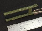
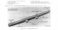
The launching-handling rail is now also built:

IMG_0822.jpegIMG_0823.jpeg

Instead of trying to fill the huge seam on it, I cut strips of thin plastic card to cover the bottom (slightly oversize, trimmed down after the glue dried) and a short piece for the top, covering only the bit of rail that will actually be visible under the missile. I had to cut away a bit of detail towards the front of the rail and rebuild it, but that was easy enough.

Clipped to the launcher erecting arm:

IMG_0825.jpeg

It stays there without glue, though to make that possible you need to file out the grooves it goes into, else the seam on the arm, inside those grooves, prevents the rail from clipping to it at all.

The missile and its rocket booster:

IMG_0826.jpeg

Separate for ease of painting. I filled the huge gaps between the corner pieces and the triangular bits of the thrust ring assembly (the open bit at the front of the boosters) because in the real world the triangles weren’t separate parts but integral to the corner pieces. This meant losing some of the rivet detail, but better not to have that, than gaps almost a millimetre wide in places.

Everything put together:

IMG_0827.jpeg

These are all the bits from the photos above, without glue because the rocket will sit on the rail that way (just — don’t bump the table :smiling3: ). All that’s missing are seven parts: tread plates over the hydraulic pistons, a hose from the rail to the nose of the missile and the four booster nozzles, all of which I’ll add after painting.

The kit also includes four rails to go on the sides of the launcher, but I’ll leave those off because I don’t intend to fix the launcher to a scenic base, and without a base, those rails will just be too vulnerable. (The rails serve to reload the launcher: the missile was assembled on the launching-handling rail in a separate building or an underground bunker, and the rail was then pushed onto the launcher via a set of rails running from the building to the launchers. Three or four launchers were set up side by side so missiles could be pushed over the first ones to get to the last. After firing, the launching-handling rail would be pushed off the launcher, away from the assembly building, so a new missile on its own rail could be pushed onto the launcher if necessary. Once an engagement was over, all of the launching-handling rails would be pushed back to the building to be reloaded.)
 

Jakko

Way past the mad part
SMF Supporter
Joined
Apr 28, 2018
Messages
10,797
Points
113
First Name
Jakko
Everything sprayed in its basic colours now:

IMG_0828.jpg

The launcher and rail got an airbrushed coat of Mr. Aqueous Olive Drab (2) while the rocket booster is their Olive Drab (1) so that there’s a difference between it and the launcher. The missile was sprayed with Games Workshop Corax White (which is a very light grey) from an aerosol can. Now it all needs highlighting, which is why I sprayed the missile grey instead of white :smiling3:
 

Jakko

Way past the mad part
SMF Supporter
Joined
Apr 28, 2018
Messages
10,797
Points
113
First Name
Jakko
Finally continued work on this by spraying lighter patches a few days ago, followed by a dark wash over the OD parts and painting the panel lines on the white missile grey, and then a drybrush with light olive for the OD parts and white for the missile:

IMG_0868.jpeg

All that remains to do is apply the markings, paint a few small bits, and stick everything together.
 
Top