Bronco 1/35 Schwerer Wehrmachtschlepper (SWS) armoured version halftrack

Panzerwrecker

SMF Supporter
Joined
Mar 2, 2022
Messages
362
Points
93
First Name
Los

This is the 2016 ‘2in1’ Bronco kit #CB35214. It was the last release of a series of SWS variants, that were based on the original Great Wall Hobby mouldings stretching back to 2009.


CB35214-CG.jpg

The detail is sharp, and the armoured cab thickness is nicely rendered to scale. Although there is a small degree of mould offset on a few parts there is no flash and very few pin marks present. It is also nice to see well thought out sprue gate connections, making removal of the access easier to accomplish cleanly.

The all-plastic sandwich design of the front wheels is most welcome as is the addition of plastic options to replace some photoetch parts. Unlike the GWH kits Bronco have included a comprehensively designed engine and although nothing will be seen if the engine hatches remain closed it is a nice feature that many modellers will utilise. The tracks are of the individual link type and although not workable they look to be of good quality. The Bronco kits also added a host of accessories that include Jerry cans and fuel drums.


in4dex.jpg
in1dex.jpgindex1.jpgindex3.jpg

Before we start the build lets have a look at some vehicle history and kit accuracy.

The Schwerer Wehrmachtschlepper (SWS; "Heavy Military Tractor") was a German World War II half-track vehicle used in various roles between 1943 and 1945. The unarmoured models were used as supply vehicles and as tractors to haul artillery. Armoured versions mounted anti-aircraft guns or a 10-barrel rocket launcher (Nebelwerfer). Fewer than a thousand were built before the end of the war, but production continued after the war of an improved model in the Tatra plant in Czechoslovakia.

Most of the GWH/Bronco variants released were actual produced vehicles, but no photographic evidence exists that either the armoured searchlight (UHU) or the armoured supply ammo (Nebelwerfer) version was ever built. Also, although images do exist of the 2cm Flakvierling 38 fitted, it was never acknowledged as an official production type. By the time the SWS was in production the 3.7cm Flak 43 was considered the more appropriate weapon.

This kit gives you options to build a supply ammo or armoured cargo version. I decided to build the produced armoured cargo version and used the Nuts & Bolts 41: Bussings schwerer Wehrmachtschlepper (sWS) and Variants as a reference guide. The book has a nice feature clearly showing all the design changes from prototype to production series by way of colour coding CAD scale images.


20220406_002246.jpg

Whilst there are many photographs of this vehicle it appears GWH used a prototype to base their original mouldings on. Although Bronco improved on many of the versions they later released, they did not address any of the updates seen on production vehicles.

Prototype

680313101bd297a0da89e8bb10e923b3.jpg

bd5814c54681dc2a58505179262dd896.jpg

Most obvious visual updates to the production vehicle include the front ‘bumper bar’ the side vision ports; the wooden platform supports, the road wheel design, the rear chassis panel components and the fuel filler cap.

The early bumper bars tapered in at the ends whilst the production series vehicles had simplified straight bars.

Schwere_Wehrmacht_Schlepper_load_carrier_and_tractor1_-_IWM_(STT_7965).jpg

The side vision ports on the kit are identical when in fact the drivers port was enlarged on the production vehicle. Compare the Flak 43 variant pic below with the prototype one above.

sws_flak.jpg

The wooden platform supports appear to have changed although photographic evidence in this area is thin on the ground. The prototype version had the platform sitting higher than the production series but how the wooden support structure changed in shape is unclear. Clear images of the prototype vehicle support show clear daylight between them yet all the images of the production vehicles I can make out appear to show a solid horizontal beam from front to back. That could just be a trick of the light so it’s difficult to tell! The supports in the kit, although of the prototype design do sit at the lower height of the production series.

20220406_002229.jpg

Compare the platform on the production vehicle image below with the prototype one on the CAD image above

armoured_lf_waffenarsenal-special34.jpg

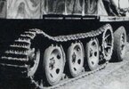
The prototype wheels had a series of holes around the edge. GWH supply the production version without the holes in the kit.

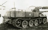
The chassis rear panel in the kit is off the prototype. The production series had the step relocated to the offside. Only one in four production SWS’s ever received a winch so if not fitted the holes in the rear panel remained.

Production rear chassis panel on an un-armoured variant

soft_rb_captured.jpg

The prototype fuel filler cap was simply screwed into the top of the tank and was obviously difficult to fill under the platform bed, so an extended ‘s’ shaped funnel extending rearward can be seen on production vehicles. (see above the step on the pic above) A tool box was also fitted next to it on many of the production vehicles.

Very few photographs exist of the interior on the armoured versions, so areas of the cab mouldings are still up for discussion. This kit does provide a split bulkhead behind the driver on the sprue trees but for some strange reason does not call it out for either of the versions in this kit. There are two issues in the kit in this area. Firstly, Great Wall Hobby research mistook the rifle racks (red arrows below) that sit on the interior walls for seats! The kit provides two folding seats for each side when in fact the split bulkhead had two slots (see dark areas behind the racks) and a rifle rack fitted which allowed the rifles to fit through the bulkhead, along the walls. Secondly the rear of the cab roof was cut short on production vehicles and a tarpaulin used to weatherproof the rear of the cab. This appears to be fitted behind the splash guard which is not present on the prototyp
e roof.

The image below from the N & B 41 book clearly shows the bulkhead in place, with the cut-outs for the rifle racks and the tarpaulin fitted to a production Flak version without the gun and carriage fitted.


7257b7c2447c796fb51d6514a7c2336d_167517.jpg

A Cad image of a prototype vehicle. Notice the rifle racks through the bulkhead cut outs.

20220406_002441.jpg

You can just make out in the image of a production Flak variant below that the roof has been cut short behind the splash guard. Interestingly the kit roof moulding does have slots to the underside of the roof. Is this so you can cut out this section on the Flak versions of the kit? It also has witness marks down the interior walls, for the bulkhead to be fitted but the instructions have you remove them!


sws_fla1k.jpg

Armoured cab instrument panel

7257b7c2447c796fb51d6514a7c2336d_167518.jpg

So, what to do about the kit’s accuracy issues?

I decided to leave my prototype shaped bumpers alone. I will trim down the passenger vision port. It won’t be quite as small as the real thing but hopefully enough to show a difference. The fuel filler neck extension can be made from heating a section of sprue and bending it into shape. The platform support update would be guesswork so the prototype design would remain on my vehicle. As for the cab, I will add the split bulkhead and add the cut outs. As the offside wall inside the bulkhead is populated with all manner of electrical gubbins I will add the welding witness marks on that side and just add a rifle rack on the driver’s side. As for the roof, there is no need to cut out the rear section. I will scratch my own tarpaulin which will effectively cover the roof area anyway
 

Attachments

  • 1fa326c942b66111d9e091d539594ee1_167777.jpg
    1fa326c942b66111d9e091d539594ee1_167777.jpg
    62.6 KB · Views: 5
  • soft_rb_captured.jpg
    soft_rb_captured.jpg
    158.4 KB · Views: 5
  • 20220406_002246.jpg
    20220406_002246.jpg
    143.9 KB · Views: 3
Last edited:

Panzerwrecker

SMF Supporter
Joined
Mar 2, 2022
Messages
362
Points
93
First Name
Los
Excellent research on this often misunderstood/misrepresented vehicle.
A very interesting post I'm looking forward to seeing this being built.
Hi Los
Well you've certainly done your research. Looking forward to the build.
Jim

Cheers guys. Indeed it is a largely ignored vehicle scale model wise. I have seen a few recent builds of the Flak versions but not many of the two variants in this kit. I'm guessing that is because they are fairly difficult to get hold of in Europe these days. I sourced mine through FleaBay from Asia and I will no doubt have to grab the unarmoured one via the same method. If I recall they are around £45 shipped which is not too bad, however there have been reports of badly damaged goods arriving from some of the chinese suppliers!
 

Panzerwrecker

SMF Supporter
Joined
Mar 2, 2022
Messages
362
Points
93
First Name
Los

BUILD TIME

With final design features decided it’s time to build:smiling4:

Steps 1 through 6 concern the construction of the chassis and suspension. The frame is a one piece moulding and the components fitted neatly together, although you do need to ensure the multipart torsion bar tubes are fitted in the correct places. I would also recommend leaving the idler axles off the chassis. Although the kits tracks are not workable, leaving them off until you finalise a good track fitment will make life much easier. The adjustment screw and nut will also need to be added once the axle is set in place.


1 to 6.jpg

One piece tub with a random selection of components fitted
20220331_202322.jpg

The front suspension/axle assembly in step 4 is quite a fiddly affair to build as per the instructions. As both leaf spring supports B72 & B73 don’t actual attach to each other, I found it far easier to attach them to the main chassis moulding first. You can then ensure that both parts sit parallel on the chassis and the remaining components added will all sit nice and square.

20220331_202336.jpg

You can move the wheels left to right, which is a nice feature, but you cannot articulate the leaf spring. It is somewhat odd that you can make certain areas of the front suspension moveable yet many connecting components are fixed:thinking: If you do want to represent leaf spring articulation as I did, simply cut the pip off part B19. This allows some movement but I also pinned it and elongated the hole it sat in for maximum articulation. Parts B8 & 9 can then be glued in place. As mentioned, the front wheel axle stubs are designed to be steerable, but the ends of each axle half (parts B65, B66) do need to be hollowed out a fair bit with a round file for the axle stubs (parts A13) to fit without forcing the two halves apart.

It’s not so apparent without the fenders present but with the wheels at almost full turn the leaf spring leans over towards the inner wheel. Notice I pinned out parts B8 & 9. I did this before realising most of the other steering components were fixed. Dohhhh! I was going to add some resin bolt heads back onto them but a large engine guard plate will hide them.
20220331_202553.jpg

You get alternatives for both front wheels, sprockets, and idler wheels. The larger Sprocket is the most common one photographed. There are two locating pins between the two sprocket halves, and you should test fit these as the teeth only align with the pins one way. The photoetched stepped ring is not fitted in the pic. It is a little short but annealing it first will hopefully make it stretch out!

20220331_202702.jpg

The sandwich designed front tyres are nice. They will only fit in the instructed order and dont forget to insert the hub before the last outer piece! Ask me how I know:flushed:


20220331_202459.jpg
 
Last edited:

Panzerwrecker

SMF Supporter
Joined
Mar 2, 2022
Messages
362
Points
93
First Name
Los
The torsion bar swing arms locate into holes in the chassis and there are pips on the rear of them to get them all to sit at the same height. If you wish to model the wheels and tracks undulated simply cut the pip off. Unfortunately, the road wheels are extremely loose on the swing arms and the location slots to attach both the inner and outer wheels together is imprecise so care will need lining them up together before final fixing. Considering how well the rest of the kit has fitted together so far, this is some very sloppy engineering! I've not decided how best to approach these issues yet so I will leave it to my last building task.


20220402_170731.jpg

The real thing. An outer wheel
1fa326c942b66111d9e091d539594ee1_167779.jpg


Diagram showing the wheel spacing amongst many other things

chassis_top_factory.jpg

Steps 7 through 9 have you adding on the chassis inner bracing panels, the fuel tank and winch accessories.

My extended fuel tank filler made from stretched sprue.

20220331_203906.jpg

Steps 10 & 11 build up the Maybach HL42 TRKMS engine. The engine looks highly detailed, but I won’t be fitting this to my kit, so I have no idea how it all fits together or into the chassis bay. What is worth pointing out is, if you do fit the engine, be aware that in step 26 the instructions have you remove a big whacking lump of plastic off the lower engine firewall on the main front fender moulding part C40. This will be much easier to do before adding all the accessories in step 13


7 to 11.jpg

Steps 12 to 20 have you build up the upper and lower armoued cab components of both variants, adding tools and all the interior fixings. You are also given alternative photoetch clasps to complete all the pioneer tools although you will have to shave off the plastic clasps first.


12 to 17.jpg

The kit's instructions have you fit both a Notek and Bosch light so check your refs as I’m pretty sure it was one or the other. Also, the driver’s side width indicator was dropped on production models.

In step 16 care is required aligning the multipart upper cab armour. The thickness of the armour is well represented so once the strengthening strips are removed from the cab top moulding part C43, it is very prone to bending. The front panel is a tight fit and the top panel is chamfered. It will all go together well if treated with care. I wasn't entirely happy with how mine fell together so I will add a little simulated welding to tidy up the joints.

Once complete, even with the small locating pins, the fit of the upper cab assembly to the fender moulding C40 is very good.

I added some vision blocks from the spares bin.

20220331_203029.jpg

Lower cab/fender sub assembly. I added some PE levers and some wiring. The kit's radio with inbuilt rack is actually upside down:disappointed2:
20220331_202815.jpg

Upper cab sub assembly with added wiring, 3D clasps, spare vision blocks and MP40 ammo. No bulkhead is fitted and the fold down seats are added. This was all before I discovered the incorrect layout and seat/rifle rack mistake. It will all be rectified in due course. Notice the rear roof cut-out slots.
20220331_202938.jpg


All the access hatches and engine panels fit well and as already mentioned, the production vehicles had an enlarged driver’s side vision port, The kit offers you two identical large drivers side port covers so the passenger one was trimmed down.

Correctly sized drivers vision port.
20220331_203304.jpg

Trimmed down passenger visor port.
20220331_203224.jpg

Armoured cab upper and lower sub assemblies test fitted together. There are only two small alignment pips both sides but it all fits well with no interference from the engine bulkhead.

Pic below shows my lower fender moulding slightly warped down on the right hand side, but it all sits flush with a little pressure.

20220331_203138.jpg
 

Panzerwrecker

SMF Supporter
Joined
Mar 2, 2022
Messages
362
Points
93
First Name
Los
Resolving the seat/rifle rack/bulkhead issues.

I have now made the cut-outs in the split bulkhead and removed the 'seats' but unfortunately as per the instructions the passenger side walls inside the bulkhead is already populated with all manner of electrical gubbins! (See red circle)


12 to 17 rifle rack interferance.jpg

Removing the 'seats' stressed me enough so I am not going to attempt to remove anything else. I have now added the split bulkhead, added the cut-outs, added a rifle rack on the drivers side and made some witness weld marks where the rifle bracket has been removed on the passenger side.

20220405_235401.jpg

As for the cab roof, I will make my own tarp once the kit is completed and once laid over, you won't know the production vehicle cut out isn’t there. That’s the plan anyway:tongue-out3:
 

Jakko

Way past the mad part
SMF Supporter
Joined
Apr 28, 2018
Messages
10,784
Points
113
First Name
Jakko
Always good to read a build by someone who clearly knows what he’s talking about :smiling3: Not a vehicle I particularly care for, but the model is looking good so far. That mistaking of the rifle racks for seats appears to be common, though — doesn’t a Trumpeter Sd.Kfz. 7/1 or /2 have the same problem?
 

JR

Member of the Rabble and Pyromania Consultant
SMF Supporter
Joined
May 26, 2015
Messages
17,275
Points
113
Location
lincs
First Name
John
My word Los that's a great introduction and subsequent build.
Most impressive research coupled with the alterations. I'll follow please .
 

Panzerwrecker

SMF Supporter
Joined
Mar 2, 2022
Messages
362
Points
93
First Name
Los
Always good to read a build by someone who clearly knows what he’s talking about :smiling3: Not a vehicle I particularly care for, but the model is looking good so far. That mistaking of the rifle racks for seats appears to be common, though — doesn’t a Trumpeter Sd.Kfz. 7/1 or /2 have the same problem?

My word Los that's a great introduction and subsequent build. Most impressive research coupled with the alterations. I'll follow please .

Thanks for the kind words chaps.

Ref the Sd.Kfz 7, seats I'm pretty confident it is the issue with the Dragon kit's, in so far as the Boxart shows the platform dropdown seat on the back of the armoured cab, but there isn't one provided in the kit!
 
  • Like
Reactions: JR

Panzerwrecker

SMF Supporter
Joined
Mar 2, 2022
Messages
362
Points
93
First Name
Los
Steps 21 through 34: The cargo platform

Step 21 to 27 concentrates only on option 1: the enclosed armoured supply ammo version and supplies all the nebelwerfer rockets that this version would likely have carried. As I am not making this one let us skip right on to step 28.

Steps 28 through 34 builds up the armoured cargo version platform. The front two thirds of the cargo sides are hanging and are represented by a plastic frame and three photoetched grilles each side. The rear outer fold down locker doors are all seperate parts and can be displayed open. The larger lower one is offered in both plastic and photoetch. I choose the easy option as the hinges looked like too much work.

28 to 32.jpg

There is a crew bench yet to add to the front of the platform (Step 31) This can be added in one of two positions; closed so the photoetch tread plate fills the void in the platform or folded open sitting in the cab.

20220402_170958.jpg

No fitment issues at all here and although the fold down side latches are moulded in, it all looks good when built up.

20220402_171013.jpg

Test fitted sub-assemblies so far.

20220402_171215.jpg

20220402_171204.jpg

20220402_171226.jpg
 

Panzerwrecker

SMF Supporter
Joined
Mar 2, 2022
Messages
362
Points
93
First Name
Los
Lining up the running gear and track construction

I’m not a big fan of the repetitive process of cleaning and assembling hundreds of non-workable tiny individual track links. I find it the most tedious part of the hobby, and a possible sub-conscious reason why I build so many wheeled vehicles. There’s no getting around it, as the only alternative is a set of Friuls, and I can’t justify spending another £30 odd quid on this kit.

The instructions state to use 112 track links per side yet the Nuts & Book states that only 110 were used. There are two sprue gates per link and a pin mark on every pin link. So, by my reckoning that’s at least a minimum of two hundred and seventy-five individual clean up steps EACH SIDE! :face-with-head-bandage:

Before I blow my mind with track construction I need to set up the running gear. My method of track construction will be to follow a sort of link and length type affair, but I first need to get the wheels lined up on the chassis.

This means tackling those nasty wheel connections and figuring a way of assembling it all, so I can paint the wheels separately. The swing arms have additional small pips on the rear which locate in the chassis. This is a nice method to ensure all the arms sit at the same height and great if you paint all the wheels in situ. I like to paint the wheels/tyres separately if possible, but the interlocking design and loose fitting connections complicates things somewhat!

After a short muse I figured it was possible to paint the wheels separately by gluing each wheel set to the swing arms first. It means dispencing with the fixed position by way of the swing arm pips but the built up tracks would effectively do this job for them as long as the pips are left on three inner and outer wheel pairs for now to line up the tracks.

One run of roadwheel pairs with the swing arm pips removed. A small gap in the oversized hole in the back of one wheel is still visable even with the swing arm inserted
20220405_235238.jpg

The contact points for connecting all the wheels is hopelessly inadequate. The two middle pairs per side are sat right up against each other, so are quite easy to align but the six inner and outer pairs are around 10mm apart. I resorted to making a quick little circular jig for these, that ensured, whilst the glue was still wet, I could twist them so they rotated in the same arc limited by the jig before drying.

With that little conundrum out of the way it was just a matter of gluing the wheels perpendicular to each swing arm. With the connection being really loose, I first added a little glue to the arm, popped a wheel pair on, left it for a few seconds, then twisted it a few times before removing it. This made both surfaces tacky and and once dry, the now rough texture afforded some friction, and they didn’t keep falling off whilst attempting to line them all up. Again, using a little jig made from some plastic stock strips I lined up all the wheels on the chassis and then glued them onto each swing arm permanently.

I deliberately left both Sprocket and idler wheels loose so I could easily ‘wrap’ the tracks around them. The sprockets use the familiar long pin into hole type connection into the chassis, and they are a snug fit so they will rotate without falling off. The idler mount on the other hand is not so simple. It uses the same engineering, but the hole is not as deep so adding the weight of the idler wheel made it continuously pop out. Having an adjustable idler is always a bonus whether using workable or unworkable tracks so I decided to drill out the chassis hole and insert a metal pin into the back of the idler arm.

A quick note on the kit's idlers. As mentioned two types are offered, but neither include the four inner guide pad linings. To compensate for this I simply cut a strip of card and PVA glued it around the centre of each. Only a fraction will be visible so it should, at least, cover the void.

Now the time has come to build up those tracks:anguished:

To fit the tracks I only really required the three inner and outer pairs with the pips left on. This way they would line up horizontaly and act as the template for the tracks.

After clean up the links do fit snugly into each other without miss-alignment, and they are, thankfully not handed. I did try slow drying cement on the curved sections of links and although I thought it would give me more time to adjust, they just wouldn't set up, so I resorted to some Tamiya fast. (green top)

I first measured the length of all five wheels and made the two lower flat lengths. Then I wrapped both the sprockets and idlers with 14 links each. (7 guide horns) leaving them to set with the aid of masking tape. Bridging the lower runs to both sprocket and idler was relatively easy, however, the top run has a huge sag which, in many images, only has the very middle wheel in contact. Over time the tracks wore out and the tension loosened, and they do appear to sag far more, sometimes onto all five pairs of wheels, and this look would be far easier to achieve.

ammo_lf_extrabox.jpg1fa326c942b66111d9e091d539594ee1_167777.jpg

Working in both 2 and 4 link sections, I eventually bridged the top length. Leaving the idler loose was a wise move, only typically, looking at the final placement of each I can confidently say I could have saved myself a whole bunch of time if I had known, by just gluing them both in the one o-clock position:rolling: That is obviously always going to be dictated by the top run tension achieved.

I left both track runs in two separate assemblies to make fitment after painting as painless as possible.

20220405_234937.jpg

With the tracks now built the pips on the remaining swing arms can be removed and voila, I can get some whacky articulation going on, and they will now be simple to fit after painting:hugging-face:

20220405_235039.jpg

The tracks did slip back off the sprocket in the next few photos and I didn't notice until I edited them:flushed: They will fit tightly once both halves are connected. I couldn't achieve the 55-guide horn links that the N & B book advised and TBH the 56 the kit's instructions called out had the idler sat behind the last wheel a touch. I ended up using 57 pin links and am happy how it looks with the track just clearing the last wheel. With a bit more patience I imagine building the top length tighter with 55 or 56 is easily manageable.

20220405_234546.jpg20220405_234654.jpg20220405_234743.jpg20220405_234837.jpg
 
Last edited:

Jakko

Way past the mad part
SMF Supporter
Joined
Apr 28, 2018
Messages
10,784
Points
113
First Name
Jakko
by my reckoning that’s at least a minimum of two hundred and seventy-five individual clean up steps EACH SIDE! :face-with-head-bandage:
This is why, these days, I clean up a bunch of track links every so often while working on the rest of the model. It’s far easier to get through them that way than by “having” to do them all at the same time because it’s the only thing holding up finishing the model.
 

Panzerwrecker

SMF Supporter
Joined
Mar 2, 2022
Messages
362
Points
93
First Name
Los
Beautifully clean work going on here Los. Superb research as well. Top stuff :thumb2:
Thanks Tim
This is why, these days, I clean up a bunch of track links every so often while working on the rest of the model. It’s far easier to get through them that way than by “having” to do them all at the same time because it’s the only thing holding up finishing the model.
This is a sane man talking. A great tip indeed Jakko :thumb2: I think after the relatively smooth and rapid assemblage of the T-Rex tracks, I found these a bit of a chore
Some excellent skills on display.
Cheers Paul

No updates on the SWS this week as I endeavour to complete a shelf queen Panther.
 

JR

Member of the Rabble and Pyromania Consultant
SMF Supporter
Joined
May 26, 2015
Messages
17,275
Points
113
Location
lincs
First Name
John
That was a text book description in my mind , very detailed reading Los .:thumb2::thumb2::thumb2::thumb2::thumb2:
 

Niho

SMF Supporter
Joined
Apr 16, 2022
Messages
398
Points
93
Location
East Sussex
First Name
Nick
Cool kit, great research and a good start, personally I'd go for the open schlepper body, i recall seeing a blurry pic of one with a PaK 43/41 in tow '45
...... which would be my way forward.
Carry on good sir
Nick
 
Top