Churchill Mk. IV AVRE with Small Box Girder Assault Bridge Mk. II

Jakko

Way past the mad part
SMF Supporter
Joined
Apr 28, 2018
Messages
10,972
Points
113
First Name
Jakko
All too much for me, going for a lie down !
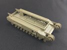
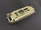
The difficult bits are done now (or so I hope … :smiling3: ). With the suspension done, for example, the rest of the hull can be built pretty quickly:

5D822FE7-EAC9-4282-A280-313E6FACD2FF.jpeg

There are some oddities to be aware of here too, though. One is that the horizontal front plate, B20, is too wide. I had put the roof in (without glue) to ensure the width of the top of the hull was right. However, with B20 in place, it pushed the sides out far enough that I suddenly had a wide gap around the edges of the roof in front of the turret ring. Filing down both sides of B20 solved that.

Another minor thing is that the instructions say to put part T3 inside the drive sprocket, so it seems to be a poly cap. However, there is no sprue T, no loose poly caps, nothing. Because there will be a plate over the sprockets, you don’t need a poly cap to hold them to the axles, but it’s odd you’re told to add a part that isn’t included. (I did search my wheels-and-tracks spares box for suitable poly caps, but only found ones that either fit inside the sprocket but not over the axle, or fit over the axle but not inside the sprocket …)

That plate that goes over the left sprocket is C11, but the instructions don’t indicate the one for the right-hand side at all — not really a problem, as it’s self-evident, but it is sloppy. They also tell you to trim two lugs off of the plate (these hold the mudscraper that sits behind the drive sprocket), but on sprue S there are two identical plates that don’t have those lugs in the first place … However, my model uses the parts with the lugs, because the tank I’m building a model of did have them.
 

JR

Member of the Rabble and Pyromania Consultant
SMF Supporter
Joined
May 26, 2015
Messages
17,388
Points
113
Location
lincs
First Name
John
The difficult bits are done now (or so I hope … :smiling3: ). With the suspension done, for example, the rest of the hull can be built pretty quickly:

View attachment 477700

There are some oddities to be aware of here too, though. One is that the horizontal front plate, B20, is too wide. I had put the roof in (without glue) to ensure the width of the top of the hull was right. However, with B20 in place, it pushed the sides out far enough that I suddenly had a wide gap around the edges of the roof in front of the turret ring. Filing down both sides of B20 solved that.

Another minor thing is that the instructions say to put part T3 inside the drive sprocket, so it seems to be a poly cap. However, there is no sprue T, no loose poly caps, nothing. Because there will be a plate over the sprockets, you don’t need a poly cap to hold them to the axles, but it’s odd you’re told to add a part that isn’t included. (I did search my wheels-and-tracks spares box for suitable poly caps, but only found ones that either fit inside the sprocket but not over the axle, or fit over the axle but not inside the sprocket …)

That plate that goes over the left sprocket is C11, but the instructions don’t indicate the one for the right-hand side at all — not really a problem, as it’s self-evident, but it is sloppy. They also tell you to trim two lugs off of the plate (these hold the mudscraper that sits behind the drive sprocket), but on sprue S there are two identical plates that don’t have those lugs in the first place … However, my model uses the parts with the lugs, because the tank I’m building a model of did have them.
Having read this , can you see why I need to lie down ?
Doesn't any one check these instructions by building a kit , quite evident they don't .It's not like these kits are cheap, think we as modellers except crap , and these manufacturers knows it .
 

Jakko

Way past the mad part
SMF Supporter
Joined
Apr 28, 2018
Messages
10,972
Points
113
First Name
Jakko
I wouldn’t go so far as to say they’re crap, but I do think AFV Club didn’t pay enough attention to the instructions for this particular kit. Too many mislabelled parts, bits that are the same on the other side left out without even telling you that, etc. Nothing that should trouble a semi-experienced modeller, but I can easily see it tripping up a novice builder. However, IMHO a novice builder should not be buying AFV Club kits in the first place, given how intricate they tend to be.
 

JR

Member of the Rabble and Pyromania Consultant
SMF Supporter
Joined
May 26, 2015
Messages
17,388
Points
113
Location
lincs
First Name
John
I wouldn’t go so far as to say they’re crap, but I do think AFV Club didn’t pay enough attention to the instructions for this particular kit. Too many mislabelled parts, bits that are the same on the other side left out without even telling you that, etc. Nothing that should trouble a semi-experienced modeller, but I can easily see it tripping up a novice builder. However, IMHO a novice builder should not be buying AFV Club kits in the first place, given how intricate they tend to be.
Fair enough on the experience of the modeller, but my point being they should be check first to ensure both the kit and instructions are correct. The fun from building a kit is soon lost when mistakes are allowed by the manufacture. We seem to except mistakes, can you imagine if you bought a self assembly item from a major shop and half of it was missing or the instructions were wrong, would you just carry on with the assembly and not go back to the shop and complain ?

This was a common occurrence with a certain brand of kitchens, always parts missing and an excess of parts you didn't need. Where are they now............gone .Why? Because customers complained.
 

Jakko

Way past the mad part
SMF Supporter
Joined
Apr 28, 2018
Messages
10,972
Points
113
First Name
Jakko
Fair enough on the experience of the modeller, but my point being they should be check first to ensure both the kit and instructions are correct.
I must now make a correction of my earlier statement:
That plate that goes over the left sprocket is C11, but the instructions don’t indicate the one for the right-hand side at all
… because I discovered they do show that, on the next page from the one that shows the left-hand side. I’m not quite sure how I overlooked it, but I think it’s because the drawings on those couple of pages all look very similar.

Still, the misnumbered parts and indicating a part that isn’t even in the kit remains odd.

can you imagine if you bought a self assembly item from a major shop and half of it was missing or the instructions were wrong, would you just carry on with the assembly and not go back to the shop and complain ?
I would continue assembling it, sure — as long as all the parts are there, it shouldn’t be too hard to figure out which goes where. It’s not like you’re building a plastic kit with a hundred different bits, after all :smiling3:

that is a very neat and logical solution to get the nose down attitude of the hull.
Thanks, but it just seems the logical way to do it to me :smiling3:
 

tr1ckey66

SMF Supporter
Joined
Mar 6, 2009
Messages
3,686
Points
113
First Name
Paul
With the suspension arm frames built, I could add them to the sponsons, as described above:

View attachment 477594

As I mentioned above, these are not that easy to fit, not only because the arms get in the way but also because the springs push the frames out of line. Best is to start at one end and glue the frame to the sponson there, then slowly work your way to the other end, though you will frequently have to go back and forth a bit to get everything lined out correctly.

Notice I left out the springs for wheels 7 and 8. This is because, as the photo of a real tank in an earlier post already appears to show, those actually extend down instead of being sprung in. From that photo, I worked out the distance between the frame and the top of the wheel for wheels No. 2 and 8, the frontmost and rearmost ones actually on the ground when carrying the bridge. This was not too hard to do by measuring the wheel diameter and the distance to the frame, because the kit’s wheel diameter is a given so it’s just a matter of dividing the gap by the wheel diameter in the photo and multiplying by the kit wheel diameter to find the size of the gap there should be on the model. And since the model will be on level ground, all the wheels between 2 and 8 just need to line up straight with them.

There is a big stroke of luck in all of this. I worked out that wheel 2 needs an 0.75 mm gap while wheel 8 needs a 4 mm gap; springing in the front wheel by 2 mm achieves just that, while the rear one needs to be extended downward as far as the wheel arm (not the spring rod) will let it. That is a downward travel of 1 mm, meaning the total difference between the two wheels is 3 mm — and with seven arms, that means steps of exactly 0.5 mm, which is really easy to do with standard sizes of plastic card :smiling3:

I modified the rods for wheels 7 and 8 by cutting off their heads:

View attachment 477596

Unmodified on the left, cut-down on the right, Note that I didn’t cut through the rod, but trimmed off the flanges to approximately the rod’s diameter, effectively making it longer and allowing it to sit further down than normal.

Then, it was a matter of installing scraps of plastic card of the correct thicknesses as spacers between the sponson bottoms and the heads of the spring rods:

View attachment 477597

Begin by adding a wheel to the arm/rod, else they will go out of alignment. After that you can easily enough stick a bit of plastic card under the front and rear of the rod’s head using tweezers and/or something you can push the spacer around with. As soon as I had one of them correct, I glued the whole thing together: blocks to the sponson and the rod head, wheel to arm and rod, arm pivots, etc.

Wheel stationSpacer thickness
22 mm
31.5 mm
41 mm
50.5 mm
6none

With those in place, I put in wheel 8 (skipping 7 for now), pushing it down as far as it would go and also glueing it in place. Wheel 7 can then be lined up easily by putting a ruler over all the arms and pushing 7 down so it hits the ruler, then glueing it in place as well.

That done, the model sits like this:

View attachment 477598

Also notice I installed sprue struts inside the sponsons. These serve to transfer the model’s weight directly onto the spring arms, instead of trusting in the glue to hold. I wouldn’t do this for other Churchills, but with the bridge and the counterweight that will eventually rest on these wheels, I don’t want the model to perhaps eventually break through its suspension.
Excellent weighted suspension Jakko! Looks just right.
Cheers, Paul
 

JR

Member of the Rabble and Pyromania Consultant
SMF Supporter
Joined
May 26, 2015
Messages
17,388
Points
113
Location
lincs
First Name
John
I've often thought that when a manufacturer plans a new kit, one person has to make the moulds, another has to write the instructions, but they're forbidden to talk to each other.
Pete
Certainly that way with many companies Pete.;)
 

Scratchbuilder

SMF Supporter
Joined
Jul 2, 2022
Messages
2,058
Points
113
Location
Luton
First Name
Mike
Good to see you sorted out the suspension. Another method for constructing the suspension if you do not have seven fingers on one hand, is to add one of the frames to the sponson first and then add the parts (plates) and arms after.
Shame about the front plate making the hull too wide for the top. This must be a flaw with this 'new tooled' kit as I cannot remember it happening to me with the two AFV Club Churchills I made.
Mike.
 

Jakko

Way past the mad part
SMF Supporter
Joined
Apr 28, 2018
Messages
10,972
Points
113
First Name
Jakko
The front plate had a fair amount of flash around it, so I’m guessing the mould may be wearing out a little there. It was nothing a bit of repeated filing and test-fitting didn’t solve, of course, but I don’t remember if the other AVRE I built suffered from this too.
 

Jakko

Way past the mad part
SMF Supporter
Joined
Apr 28, 2018
Messages
10,972
Points
113
First Name
Jakko
After I also attached the bridge-carrying bracket to the hull front yesterday, I could work out the counterweight needed in the hull to balance the bridge. I first tied that to the tank with some copper wire and then put in enough weight so it didn’t tip forward anymore:

00872363-485C-42CF-A66F-B6CE9C7D402A.jpeg

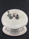
This turned out to be:

E521E764-81D2-4381-9AD8-F4F03009C032.jpeg

One Captain Carrot, one Sergeant Angua, one Susan Sto Helit, and one Luggage. And though I was sceptical about AFV Club’s recommendation of 100 grammes, I was wrong:

6E851629-6FB3-4E46-9359-3C448EA2A209.jpeg

Now to find some material to replace this temporary crew with.
 

Jim R

SMF Supporter
Joined
Apr 27, 2018
Messages
13,865
Points
113
Location
Shropshire
First Name
Jim
14ef7fc0-44f8-4566-9730-0ec9e082c099-jpeg.477598


Getting to this stage with the stance just right was a labour of love and skill. Fascinating to see how you did it.
 
Last edited:

Jakko

Way past the mad part
SMF Supporter
Joined
Apr 28, 2018
Messages
10,972
Points
113
First Name
Jakko
Really? That was the easy part, if you ask me — attaching the assemblies with the suspension arms was difficult, adjusting the arms is far easier here than on most kits I’ve had to do similar things to :smiling3: Of course, if it hadn’t been a simple multiple of 0.5 mm for every step, it would probably have turned into a lot more work.

The hundred grammes was also easy enough:

F40CE738-FAA5-4A3B-82B4-204DF1089662.jpeg

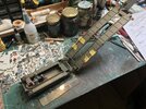
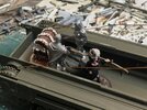
This is roofing lead, cut and folded (using a big hammer :smiling3: ) to fit, and held in place with some plastic H-profile and bits from the kit’s sprue. That let me add the rest of the basic hull shape:

958236F8-C7F4-4C1D-81FF-8B2DA334559B.jpeg
 
Last edited:

Waspie

SMF Supporter
Joined
Mar 13, 2023
Messages
2,714
Points
113
Location
Portland - Dorset
First Name
Doug
After I also attached the bridge-carrying bracket to the hull front yesterday, I could work out the counterweight needed in the hull to balance the bridge. I first tied that to the tank with some copper wire and then put in enough weight so it didn’t tip forward anymore:

View attachment 477776

This turned out to be:

View attachment 477777

One Captain Carrot, one Sergeant Angua, one Susan Sto Helit, and one Luggage. And though I was sceptical about AFV Club’s recommendation of 100 grammes, I was wrong:

View attachment 477778

Now to find some material to replace this temporary crew with.
WOT!!! No Commander Vimes?
 

adt70hk

I know its a bit sad but I like quickbuild kits!!!
SMF Supporter
Joined
Sep 4, 2019
Messages
9,526
Points
113
First Name
Andrew
Great work Jakko. Will best the suspension assembly process in mind when I get to mine!
 

Scratchbuilder

SMF Supporter
Joined
Jul 2, 2022
Messages
2,058
Points
113
Location
Luton
First Name
Mike
Jakko,
That did make me laugh out loud with your method of weight calculation.
Make sure that the winch frame is really dry and secure before testing/attaching the bridge. On my original I did not leave it to dry out thouroghly and as soon as I let the winch take the weight, the bridge pulled it off the frame. Luckily it was only a case of glue and wait.
Cheers
Mike.
 

Jakko

Way past the mad part
SMF Supporter
Joined
Apr 28, 2018
Messages
10,972
Points
113
First Name
Jakko
WOT!!! No Commander Vimes?
I don’t have him, so sorry, no … I would have added Rincewind and/or Death, but these four were enough already :smiling3: And well, I also have Detritus, who I put on the rear of the tank first, but he seemed to be clearly too much. When I weighed him after taking the photo of the scales above, he turned out to be about 230 g, IIRC.

Will best the suspension assembly process in mind when I get to mine!
It’s really not that difficult, but you need to keep your eyes open to get it all on straight.

That did make me laugh out loud with your method of weight calculation.
Goal achieved ;) TBH, I first wanted to use some other stuff, but then my eye caught those figures that have stood un-, half-, and nearly fully painted on my workbench for years and I thought: if I’m going to take a photo of it anyway, why not? :smiling3:

Make sure that the winch frame is really dry and secure before testing/attaching the bridge. On my original I did not leave it to dry out thouroghly and as soon as I let the winch take the weight, the bridge pulled it off the frame. Luckily it was only a case of glue and wait.
Good point, I had thought of that too already, but it bears repeating. This is also why I glued the front support to the tank yesterday evening but waited until this afternoon to work out the counterweight … um … weight. These things need to be fairly strong, and you don’t want them being pushed out of true or pulled off the model because the glue hasn’t dried enough yet.
 

Jakko

Way past the mad part
SMF Supporter
Joined
Apr 28, 2018
Messages
10,972
Points
113
First Name
Jakko
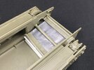
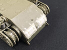
At the rear hull, I decided to first add part of the waterproofing gear that AFV Club didn’t include:

IMG_9562.JPG

This was done by glueing pieces of 0.5 mm plastic card into the openings, then taking slightly smaller pieces of 1.5 mm card and filing their edges and corners to a slope. The tape-like stuff over them is my old standby, Tamiya Pla-Paper, paper-thin plastic card that I cut into strips and glued in place with a lot of liquid cement. The lower towing eyes have got a small plug in them, which I made by punching a 1.4 mm disc from some plastic card.

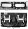
All of this is pretty much exactly as per the official instructions, because when I had the idea to build an AVRE with a fascine as used at Westkapelle about a year and a half ago, I contacted Peter Brown (who used to write plenty of articles about British vehicles and units in Military Modelling) to ask if he had information on the deep-wading gear. He obliged me by sending a scan of a British Army manual titled 6-ft Wading Instructions for Churchill I–VI which has the exact procedures for making the real tank watertight :smiling3: Here are the relevant images for this part:

Churchill 6ft Wading Instructions p. 21.jpeg

Two metal lids, seen in the top picture, have Cordtex (detonating cord) with an electrical detonator taped inside of them, the lids are then welded to the tank (not all the way around, just enough to keep them on) and the seams are then closed with contact cement, watertight tape and what I think is a kind of liquid sealant. The detonator is wired to the tank’s tail light (!) so that the covers can be blown off the tank after landing, simply by flipping the light switch.
 

adt70hk

I know its a bit sad but I like quickbuild kits!!!
SMF Supporter
Joined
Sep 4, 2019
Messages
9,526
Points
113
First Name
Andrew
Coming on nicely Jakko she very good of him to share that with you.
 
Top