Quickie: Takom M29 Weasel

Jakko

Way past the mad part
SMF Supporter
Joined
Apr 28, 2018
Messages
10,791
Points
113
First Name
Jakko
As mentioned elsewhere, I now have not one or even two, but altogether five M29 and M29C Weasel kits … And as mentioned there, part of the blame for that lies on a YouTube video of a review of the Takom kit which raised questions — questions about the review, that is.


When someone complains that a model is hard to build, it usually leaves me thinking that I would like to see for myself how bad it really is. This time, I submitted to that and purchased Takom’s M29. I got it in the mail yesterday, and extraordinarily, I already started it last night :smiling3: The LCA is on hold for the moment.

Takom M29 Weasel.jpg

One small mistake with the box-top painting is that the vehicle is in motion here (see the mud coming off the track) but you can’t drive a Weasel with one arm out the window … It has two steering levers, so the driver would need to push both of those forward to get the vehicle to move. But it looks good :smiling3:

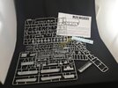
Here’s what you get in the box:

IMG_0156.jpeg

The instructions are on Scalemates, for those who want to follow along. I decided to follow the YouTube video and build the model according to the order of the instructions, starting with the first step and proceeding towards the last one, instead of doing what I usually do and decide for myself on the order in which I add bits to to the model. This mainly because it looks like that’s what the chap in the video did as well, and I want to discover if the problems he had with the kit were caused by Takom, or by himself.

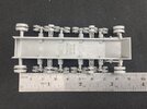
Step 1 is the underside of the hull with the suspension and the supports for the return rollers and idler wheels. After building most of that step, you end up with this:
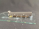
IMG_0157.jpeg

That looks simple, but it’s quite a lot of work: it took me over three quarters of an hour to separate, clean up and fit the parts. This, by the way, is the left-hand side: the bit sticking up on the left is the front of the vehicle. What you can see here are 19 parts: hull plus 18 for the suspension etc. on this side — so another 18 on the other side. Each of the return roller supports is three parts, and for the rear one you need to take care that you don’t fit its axle (A16) upside down, because you can. The arm for the idler wheel is four parts (arm, leaf spring, saddle for the spring, and support on the hull that the spring sits against), while along the lower edge there are four separate leaf springs (A20) and the covers over them (A22).

Those springs are the biggest problem here: you have to take care not to break off the end when you clean them, and they fit very loosely into the hull. The spring is attached to the sprue near its outboard end, but if you try to clean up the attachment point by slicing it off lengthwise, from the inboard side out, you will break off the end of the spring. Better to lay it flat on its side on your work surface and cut the attachment point off from the side.

Once cleaned, the springs have a lot of play in the hull, both up and down, and forward and back. Take care to get them at right angles to the hull and not up against the covers A22. On the real Weasel, those serve as bump stops, so if you glue the springs up against them, the suspension is compressed all the way. This is why I’ve put the hull onto a few bits of balsa on a pane of glass: so that I can press all suspension arms against the glass and get them at the same height. (My thoughts are that the man from the video had half a link too many in his tracks because he did glue the springs against the covers, but I can’t see whether or not he did in the video. It would neatly explain his problems with the length of the track, though.)

In step 1 you also get to fit the upper suspension arms, in the rectangular slots above the springs, but I left them off for now because otherwise it will be very difficult to line them up correctly with the bogies that will only be built and fitted in step 2, and it was getting too late last night for that. Why? Well, four bogies with two axles each, and each axle has two wheels on the inside and two on the outside. With three other parts per bogie plus the upper suspension arm, that makes for 96 parts to clean up and fit. I didn’t feel like doing that anymore late last night :smiling3:
 
Last edited:

Andy the Sheep

SMF Supporter
Joined
Apr 7, 2019
Messages
1,533
Points
113
Location
North Eastern Italy
First Name
Andrea
I'm joining the audience: Takom's suspensions are (yes, they are while I'm wishing they were ;)) my worst nightmare building their BV206.
 

Jakko

Way past the mad part
SMF Supporter
Joined
Apr 28, 2018
Messages
10,791
Points
113
First Name
Jakko
Maybe he's pushing the left hand lever with some other part of his anatomy :rolling: :tongue-out3::thinking:
Well, I guess he wouldn’t need to keep his left foot on the clutch all the time … ;)

Takom's suspensions are (yes, they are while I'm wishing they were ;)) my worst nightmare building their BV206.
This afternoon, I assembled 64 wheels onto eight arms, and this is about as fiddly as on the LZ kits. The chief advantage here is that the parts are plastic, so you can use model cement instead of superglue and that gives more time to line the wheels up reasonably well. I doubt you’re going to get them all lined out perfectly unless you spend an inordinate amount of time on it, though.
 

Jakko

Way past the mad part
SMF Supporter
Joined
Apr 28, 2018
Messages
10,791
Points
113
First Name
Jakko
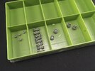
I built all the bogies and the remaining wheels, except for adding the etched brass rings that go into the idlers to represent the lip on the inside:

IMG_0159.jpeg

As you can see, it’s almost undoable to get all eight wheels on a bogie nice and straight on the beam with the axles (FYI, each of those wheels is about 5 mm in diameter). After doing that, I completed the bogies by glueing parts A19 and A21 to the middle of the beams. It turned out, after doing a few, that the (relatively) easiest way was to first attach the incredibly small A19 and only then the larger A21, instead of the other way around like I did for the first couple. It’s then still so immensely fiddly that I actually prefer LZ’s parts here, because at least there this is all one piece. Takom should just have done that too: mould the beam together with the upper bogie body in one piece instead of three in order to make the whole thing movable for those modellers even more insane than me.

Then to fix it all to the hull … First, I installed the upper suspension arms A24, then added the bogies.

That’s to say: I wish :sad: Takom’s idea is that the bogies click onto the ends of the leaf springs: they have little dimples on both sides, and there are two corresponding pips inside the square opening that runs through A19. But if you try to push those pips into the dimples, you break everything because that requires a lot more force than these fragile parts can take :sad: I cut away the pips and then it largely worked. Also make sure that absolutely all traces of the three sprue attachment points have been removed from all eight A24s, because all of them interfere with the correct fit of these bits.
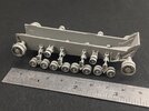
IMG_0160.jpeg

The rings have been added here, and they fit poorly (they fall into the wheel too far) and are also very fiddly to install, plus I think they will hardly be noticeable, so I think you might as well leave them out entirely. Takom would have done better to mould the whole outside of the wheel separately, so that the ring could have been moulded in, like for example with their recent M48 MBTs.

If you look closely here, you can see that the second bogie from the right has a green part at the end of the spring. This is because the end broke off and disappeared without a trace (this being the first spring I cleaned up, and on which the end half-broke off when doing that). I quickly fabricated a piece from scrap material and glued it in its place.

Lining the wheels out is basically SNAFU:

IMG_0162.jpeg

I can’t get them any better than this :sad: The chap from the video also mentions it, and the problem is definitely not him. Yes, I will happily believe that there are people who can get them all lined out perfectly, but they have a lot more patience than I do, and probably also less reduction over the last few years in their fine motor skills. But even if I account for the latter, I think this part of the model has been executed exceedingly poorly. Of course, it’s all very tiny and delicate on the real vehicle, but Takom, that doesn’t mean that you couldn’t have simplified it so that everything is easier to assemble and get straight.
 

Jakko

Way past the mad part
SMF Supporter
Joined
Apr 28, 2018
Messages
10,791
Points
113
First Name
Jakko
After thinking about it a bit more, my advice to build the suspension would be to first build the bogies, meaning parts A19, A21 and A23, and only then add the wheels. I also think it’ll be better to click the leaf springs A22 into the bogies before glueing them to the hull (and again, before adding the wheels), because that avoids the problem of having to somehow fit the bogies to the springs while there are all kinds of bits on them that want to move because the glue hasn’t set yet. Waiting for the glue to dry isn’t a good idea either, because then the wheel arm A23 may end up fixed at an angle or something, keeping some of the wheels from touching the ground.

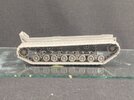
I just installed the left track:

IMG_0163.jpeg

This is almost as much of a chore as the bogies :sad: First of all the most important advice: don’t remove all track parts from the sprue beforehand! Almost all of the parts are designed to fit in a specific place and a specific direction, which the instructions don’t make all that clear in step 3. Start with link A31 on top of the drive sprocket — it goes over the tooth that’s at the top — and then work your way along the rest of the track (though I fit A28 first and then continued clockwise from A31).

I didn’t need a half-link like the chap from the review video, but it was close. I had to push the parts closer together to get the track to fit reasonably well.

But there is something strange going on here:

IMG_0164.jpeg

The right track (bottom of the photo) is loose on the wheels here to illustrate the problem: both of the tracks toe outward at the rear of the vehicle. I already pushed the left one in a bit, which worked fairly well, but it was just as bad as the one on the right.

I can’t work out if this is me or the model. I would think it’s my fault, for not lining up the bogies correctly, but at the same time, I wonder why they both toe outward on the same side of the vehicle, and by about the same amount.
 
Last edited:

Jakko

Way past the mad part
SMF Supporter
Joined
Apr 28, 2018
Messages
10,791
Points
113
First Name
Jakko
Once the glue had set a bit, I added the other track too:

IMG_0165.jpeg

This took about half the time and the effort of the other one, so it looks like practice makes something that may pass for perfect if you forgot to put on your glasses. That is to say, the fit of the track is only barely satisfactory, and I think I will need to pay closer attention when I have to do this for real on the second kit, that I’m going to convert to an M29C. (Which is to say: by now, I consider this kit mainly a test build to learn what not to do.)

Also, the angled stance of the track somehow corrected itself without the need for the fairly heavy pushing I had to do on the other side, but don’t ask me how.
 

Jim R

SMF Supporter
Joined
Apr 27, 2018
Messages
13,724
Points
113
Location
Shropshire
First Name
Jim
Takom have definitely got that running gear wrong. There's certainly a better way. You've done very well to have got an acceptable result. I hope the rest builds up easier. What you have so far looks very fragile so try not to sneeze :smiling:
 

Jakko

Way past the mad part
SMF Supporter
Joined
Apr 28, 2018
Messages
10,791
Points
113
First Name
Jakko
What they did was try and make it as accurate as possible, but in doing so, overcomplicated the model to the point where it is difficult to build. What something like this needs is a Tamiya solution where there are fewer parts, that just slot together. Not every part separate like the real thing.
 

Jakko

Way past the mad part
SMF Supporter
Joined
Apr 28, 2018
Messages
10,791
Points
113
First Name
Jakko
Step 4, we’re past the suspension!

IMG_0167.jpeg

Guess the addition! What got added in step 4? Well, the axle between the idler wheels, inside the bow. That’s it. All of step 4 consists of installing that axle. :smiling3:

Step 5 is equally complicated:

IMG_0168.jpeg

Oddly, the floor consists of three pieces: a central part with the frames and slats on the sides, and a plate on each sides that goes underneath the frames and slats. I didn’t quite understand the reason for moulding this as separate parts when it can just as easily be made as one, until I noticed this:

IMG_0169.jpeg

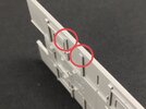
There are tiny bevelled edges to four of those slats, two on each side, so to mould those, the floor has been made as three parts. But what are those good for?

That turns out to be this:

IMG_0171.jpeg

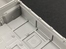
The lower edge of the side panels is angled inward, and the bevelled slats fit neatly over that.

WTF?!

If they had instead put little indents into the angled lower edge, the whole floor could have been one piece. But that also goes for the slats that you can see on the side wall here: this is a separate part that has to be glued to the side wall, but there is no reason at all to mould it like this! There are no undercuts, so it could just as easily have been moulded integrally with the wall.

Around this point, I decided that following the instructions step by step is a road that leads to madness. Step 6 sees the construction of the engine cover and the radiator with some walls around it, completely in the void when both of these need to fit together with the floor, walls, etc. I did try, but you can’t build them properly without dry-fitting them into their eventual locations and leaving them there until the glue dries. But that in itself is only barely doable: if you put the floor loose onto the lower hull, you will need more than two hands to keep the floor in place and hold the radiator correctly in place. This applies even more so to the engine cover. So I eventually decided to do it my way after all:

IMG_0170.jpeg

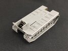
The floor has been glued to the lower hull here, and the radiator with its walls has also been glued down. I also painted the visible parts of the lower hull with olive drab.

My impression of this kit so far is twofold: too many parts that make it unnecessarily complicated, and the instructions have been written by someone who probably never built a plastic kit outside of a computer.

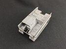
Next, I fitted the interior bulkhead and the side walls, which have to be added together because the bulkhead ensures the correct location of the walls, and keeps them vertical. Then I also added the engine cover:

IMG_0172.jpeg

The additional board on top of the right side wall (the one on the left still needs to be fitted) is another example of unnecessary parts: you have to glue this to the side wall, but there is no undercut or anything else that necessitates this being separate. It could have simply been moulded integrally with the wall with no loss of detail, but a gain in ease of construction.
 

Jim R

SMF Supporter
Joined
Apr 27, 2018
Messages
13,724
Points
113
Location
Shropshire
First Name
Jim
Well you're getting there despite Takom's best efforts to thwart you. Although there are issues with the kit the result looks to be very well detailed.
 
Last edited:

Jakko

Way past the mad part
SMF Supporter
Joined
Apr 28, 2018
Messages
10,791
Points
113
First Name
Jakko
It is very well detailed — to the extent that they give you parts that are unrealistic to expect people to add, IMHO. For example, if you look at step 11 of the instructions, you’ll see parts TP5, which is to say: they expect you to roll two pieces of etched brass into a round shape, so you have basically half a tube. Those are no more than a couple of millimetres on a side when flat … how on earth are you ever going to make those properly half-round?
 

Jakko

Way past the mad part
SMF Supporter
Joined
Apr 28, 2018
Messages
10,791
Points
113
First Name
Jakko
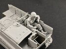
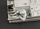
I built the driver’s area, which is far fiddlier than it looks in the photos:

IMG_0173.jpegIMG_0174.jpeg

Fitting the left-hand sidewall was a minor mistake, as it made installing the various levers a lot more difficult than it needed to have been — something else to keep in mind for the next one :smiling3:

The driver and his seat are still loose, for painting, though I kind of wonder if I will be able to get him back in once the front is on, because it’s already a little difficult now. Takom gives you two versions of the right-hand steering lever: one normal and one with the driver’s hand moulded on. In typical fashion, the instructions tell you to glue the lever with the hand to the vehicle rather than to the driver, but I stuck it to his wrist instead. If it should end up slightly out of place near the floor, that will not be anywhere near as obvious as when there’s a gap at his wrist instead.

There is also an etched part to go around the gearshift lever. I had added it, but because its location is a bit hazy, Inhad to remove it again to fit the levers to the floor. As I then built the driver, I didn’t want to pull him out before the glue dried, so I’ll refit the etched bit later on.
 

Jakko

Way past the mad part
SMF Supporter
Joined
Apr 28, 2018
Messages
10,791
Points
113
First Name
Jakko
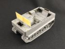
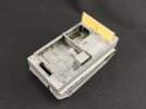
The finishing line is in sight:

IMG_0175.jpegIMG_0176.jpeg

All of the major parts are now assembled, I just need to add a number of details parts and it’s done. I had some trouble fitting the rear plate as well as the small front and rear decks, though nothing that some clamping and tape to pull them together didn’t fix. Once again, though, it’s making me think that leaving off the left side until you’ve finished the interior, and can then add the remaining outer panels, may not be a bad idea.

The windscreen is still loose, and it’s the only part where I really had a fairly difficult time getting it to fit. It kept getting pushed forward by the engine cover, so I had to scrape the forward edge of that down a fair amount. By the time the windshield fit reasonably well, but was still being pushed forward a little, I noticed there are some bolts on the back of the windscreen that are in the way of the engine cover. Shaving them off solved the last part of the problem. A missed opportunity by Takom here is that the windshield can’t be built as folded down.

I’ve also built the seats, but they’re still loose too.

Here’s an extra tip: how to get the driver in and out without putting strain on the levers:

IMG_0177.jpeg

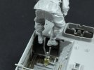
Put his feet under the front deck and move him forward and down while rotating him backwards. You can also do this (just) with the windshield in place.
 

Jakko

Way past the mad part
SMF Supporter
Joined
Apr 28, 2018
Messages
10,791
Points
113
First Name
Jakko
Not yet, I need to add a good number of small parts first :smiling3:
 

Jim R

SMF Supporter
Joined
Apr 27, 2018
Messages
13,724
Points
113
Location
Shropshire
First Name
Jim
You've done well to get this far. It looks neat and tidy. Glad the driver can be made to fit. It looks fragile enough already but if you've got a lot of small parts to add you're going to find holding it for airbrushing very awkward.
 

Jakko

Way past the mad part
SMF Supporter
Joined
Apr 28, 2018
Messages
10,791
Points
113
First Name
Jakko
Luckily, most of those are on the inside :smiling3:
 
Top