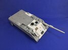
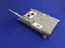
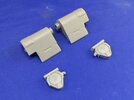
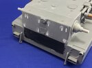
JPK 120 in 1:35

Jakko

Way past the mad part
SMF Supporter
Joined
Apr 28, 2018
Messages
10,958
Points
113
First Name
Jakko
Certainly using up the contents of the spares box.
To be honest, not really :smiling3: The Leopard hatch comes from the kit I bought specifically for this, that also donated the suspension parts. The only bits from the spares box so far are the commander’s periscopes and the brown block on the glacis plate, that will be gunner’s sight.

Work looks very neat. A lot of thought as to what was likely - your ideas on the autoloader access makes total sense.
Thanks, as I said before the idea is to make it as it actually might have been in service, rather than just going by what looks cool and impressive.

The usual well thought out construction going on here Jakko. Nice one.
Thanks :smiling3:

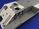
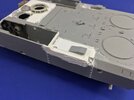
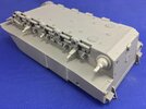
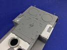
On to the latest work :smiling3: On the engine deck, I replaced the moulded-in handles (Tamiya style) by copper wire, and also built the basic shape of the hatch on the left-hand side:
DB2A8BCD-041A-45B1-A1DB-22A2079230E9.jpeg

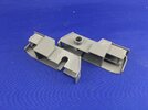
The grey wedge on both was a single kit part that was to go on the right-hand hatch (open ends front and rear, low part in the centre), so I cut it in half and used it on both sides, opening to the rear on both.

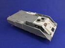
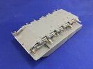
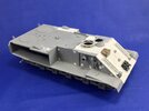
I then glued the upper hull to the lower:
1313204E-4749-4EEA-8A2B-3D0CA12BCA8A.jpeg

For this I stuck the gun pods and the side panels on without glue, then carefully glued the hull halves together and once I was sure the sides also lined up correctly, removed them again. This is pretty much necessary because the gun pods will be trapped between the hull and the side plate, there is no way to remove them once the sides are on. If I’m to get any paint in there at all, it will have to be before I glue the sides on, but I need to finish building the gun pods first — for which I’m waiting for a second gun barrel that someone said I could have.
 
Last edited:

Jakko

Way past the mad part
SMF Supporter
Joined
Apr 28, 2018
Messages
10,958
Points
113
First Name
Jakko
Then here’s another mod :smiling3:

The design of the gun pods is poor, because you need to install them together with the side plates, meaning you either have to paint all this first, or you have to keep it all loose until after painting. In my case, because of the alterations I’m making to the left rear deck, I would also have to either fabricate stuff on two pieces and have it all line up nicely, or paint first and then add stuff to bits already painted.

After wracking my brain for a good while, I came up with a number of ways to solve this, to allow the guns to go in after painting. The one I settled on is:

22DDF3A1-5443-43C9-B91E-7A9C121D3D0B.jpeg

I sawed the bit of pipe off the gun pod, filed the area flat and the sawed a slot below each of the two pivot holes. The slots are slightly narrower than the holes, so that the pod clicks in place over the axle pegs on both sides.

That done, I stuck the pipe on the axle it would have gone over:

15BDE285-3D4C-4476-9709-C4ECCFD2FBDB.jpeg

Then pushed it as far as it would go with the gun pod and glued it in place. I can now add the outer plates and then slot the gun pods in after painting. Before I do, though, I’ll need to add some paint under the overhanging roof bits, as they will be hard to spray later on.
 

Jakko

Way past the mad part
SMF Supporter
Joined
Apr 28, 2018
Messages
10,958
Points
113
First Name
Jakko
Read on for some more of that, if I say so myself :smiling3: First, having modified the gun pods and painted under the overhangs, I could glue the side plates to the hull:

9A5C227F-A71B-4BF2-8AA4-4D9F1B69BBE9.jpeg

And then I could build up the hull around the new bit of rear deck:

911E3293-32A9-4560-9E02-3D5F62CFD3AF.jpeg

The putty still had to dry before I can sand it all flat, of course.

Eventually, it dawned on me that trying to move twelve wheels inward by 0.5 mm was far more troublesome than moving eight wheels outward by 0.5 mm, so:

62FCDBFF-5A5E-4BF8-A05A-E2769EE6F224.jpeg

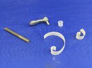
… I punched some discs from 0.5 mm and glued them to the drive sprocket and return roller axles, so they’ll sit slightly further out than normally. That just left the problem of adapting the 3 mm poly caps to the 2 mm axles. I tried a number of different things:

BEBD2AAC-769B-4BD0-8843-DB35BBDE857F.jpeg

On the left is a piece of 3 mm sprue with a hole slightly over 2 mm drilled into it on a lathe. This works, but it’s pretty laborious, because you can’t just drill a long tube and chop it into lengths, and if you’re not careful, the tube will split or buckle or go wrong in some other way. Another thing I tried was wrapping plastic card around the axle, as has been mentioned earlier in this thread. The bit in the middle is 0.13 mm (according to the packaging), the other is about half that (it’s Tamiya Pla-Paper, which my non-digital callipers say is slightly over 0.05 mm). The thicker plastic didn’t work because it’s not flexible enough, the thinner is but it’s very hard to roll it up just tightly enough, even when using some 2 mm rod to roll it before it goes onto the axle.

Another thing I thought of, was to glue bits of 0.5 mm strip or rod around the axles, but I discarded that as being far too fiddly and laborious.

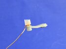
And then my eye fell on:

F6E8024F-84E7-4713-B76D-7B3CBF10AF44.jpeg

… a roll of 0.5 mm copper wire! Wrapping that around the 2 mm rod gives a coil that can easily be put onto the axle, and the poly cap then grips it tightly. About the only drawback seems to be that it might pull the wire off the axle even if I glue it to that, but that just means I shouldn’t test-fit the wheels much, or at all, and I can live with that :smiling3:
 

Tim Marlow

Little blokes aficionado
SMF Supporter
Joined
Apr 27, 2018
Messages
16,889
Points
113
Location
Somerset
First Name
Tim
Cool logical thinking going on there. Nice one Jakko. Just out of interest, do you think it would have been possible to bush out the poly caps with some 0.5mm walled 3 mm tube, or even bush out the whole part with 2mm bored brass rod of the right diameter? Just wondering about another way of looking at the problem seeing as you have access to a lathe, and brass is far easier to work accurately than plastic ;)
 

Jakko

Way past the mad part
SMF Supporter
Joined
Apr 28, 2018
Messages
10,958
Points
113
First Name
Jakko
I had thought of that too, more or less (I would have glued 3 mm tube over the axles) but I couldn’t find any suitable tube on a fairly quick look, and given that mail-ordering just one length of tube is very uneconomical, I must admit that didn’t really look too hard. The lathe is my father’s, and he also had no suitable material, unless you count brass that would need to be turned down a fair amount to even get to 3 mm, but then you’re looking at as much work as boring out sprue, if not more …
 

Jakko

Way past the mad part
SMF Supporter
Joined
Apr 28, 2018
Messages
10,958
Points
113
First Name
Jakko
All the axles now have a nice coil of copper wire:

9B9A1A1B-BDA6-4C85-9590-23045E230E7E.jpeg

And let’s have an overview of where the model is at now:

D072BA85-DDD5-4327-B7CE-6E0555048F7B.jpegCE93AD40-1174-4328-849C-38EA2625520C.jpeg

I completed the major work on the area around the left hatch, so now there are no more major constructions to be done and I can get on with adding details.

Oh yeah, the gun pod on the right is too loose, and drops down at the back without a gun barrel (as here) but at the front if I do put one in. I guess I’ll have to balance it with some weights once the model is almost finished.
 

Scratchbuilder

SMF Supporter
Joined
Jul 2, 2022
Messages
2,051
Points
113
Location
Luton
First Name
Mike
Jakko,
This is coming together very well. Enjoying the modifications you are adding,
Mike.
 

Jim R

SMF Supporter
Joined
Apr 27, 2018
Messages
13,848
Points
113
Location
Shropshire
First Name
Jim
Excellent problem solving. The wire trick is a really clever solution. Certainly makes the build interesting.
 

Jakko

Way past the mad part
SMF Supporter
Joined
Apr 28, 2018
Messages
10,958
Points
113
First Name
Jakko
Thanks :smiling3: I’ve moved my attention to the rear of the hull. The VT 1-2 had large exhaust things that I suppose held silencers or something, but I’ve not discovered their precise reason for being. In any case, I don’t particularly like the looks of them:

00931F41-CBB7-4FDE-AF0B-423E63487B00.jpeg

Top/left are the VT 1-2 exhausts, bottom/right are those from a Dragon KPz 70, that I had surplus to requirements, and I decided to fit those because they just look better and are a realistic choice.

First, I filled all the holes in the rear plate for them, and for the towing eyes, as well as painted the area behind the air exhaust grill black:

4B774072-7A43-49D7-9583-D6439FEBB7C5.jpeg

Then I glued stuff to it :smiling3:

3AC59A36-B356-464B-A06E-7E18C277C839.jpeg

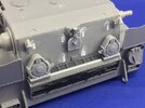
I cut a small part from the lower end of the grille, because that would have closed the gap between the original exhausts but is far too narrow for the KPz 70 ones. I’ll need to build something to replace it, of course. The tow hooks are from the Leopard 2 kit, the infantry telephone (the round box) came with the VT 1-2.

It still needs some more, like that shield with the white cross that’s on most German vehicles (it serves for night-driving) and maybe a few other bits, depending on what I can find and is plausible.
 

Jakko

Way past the mad part
SMF Supporter
Joined
Apr 28, 2018
Messages
10,958
Points
113
First Name
Jakko
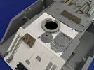
On the crew compartment roof, I added some lifting eyes from the kit as well as punched bolt heads so it would be removable, like on the real thing:

82CFA2B2-4F4C-4935-A696-EA17AA2B9100.jpeg

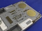
You can tell there that I also put tools onto the engine deck:

59F0E9C2-FFAB-4010-BD28-56DF9A72ADD6.jpeg

These are all spares from an Italeri Leopard 1, which I converted long ago to the Dutch Army version, that carried its tools in bins along the hull sides. I just arranged them on a roof in places that seemed logical, moved them around a bit to improve the positions, and when I was happy with it, ran some glue under them.

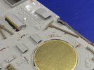
As you can see, I also added the etched brass intake grilles, after painting black underneath them. I also engraved some panel lines around the autoloader hatches, so they sit on removable roof pieces and added bolt heads along their sides to show this more clearly.
 

Jakko

Way past the mad part
SMF Supporter
Joined
Apr 28, 2018
Messages
10,958
Points
113
First Name
Jakko
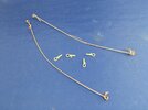
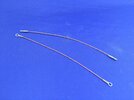
I made two tow cables:

E1B82DCB-5166-438B-8851-E53060D4569B.jpeg

These are from thin copper wire I took from an electrical cable and twisted together with a hand drill. The eyes are from the Hobby Boss Leopard 2 kit. After cutting the cables to 13 cm long, I glued on the eyes:

22969823-2361-41C2-922B-7E619623EA59.jpeg

I arrived at this length by measuring up a tow cable in the drawings of a Belgian Leopard 1A5 in Michael Stackpole’s Leopard 1 Trilogy, which seemed to fit well with the 13 cm that Hobby Boss recommends in the Leopard 2A4 instructions.

On the engine deck, I added two hooks and a post on each side:

F2F079B4-1DFA-43FA-8F04-55973784DD56.jpeg

To make sure these will hold the cable in place, I drilled holes through the engine deck and made the hooks from 0.5 mm copper wire while the post is 1 mm plastic rod; once the cable is on, I’ll glue a little crosspiece on the top to make it a T-shape.
 

Jakko

Way past the mad part
SMF Supporter
Joined
Apr 28, 2018
Messages
10,958
Points
113
First Name
Jakko
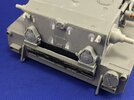
I was pondering how to make the extra bit of grill at the rear, between the engine exhausts, and didn’t really fancy scratchbuilding something from strip. Looking through my generic 1:35 spares box, I found an unexpected solution:

ACE72759-6324-4815-BF67-6721211BE890.jpeg

The darker grey grill is from some T-34 kit, that somebody 20+ years ago gave me a handful of parts for (a complete turret and some other bits), and it fitted nearly perfectly in the space left. All it took was a bit of plastic strip to close the gap between the two grilles.

I also added the night-driving shield, which also came from the Dragon KPz 70.

That done, I turned back to the gunner’s sight:

DA6F0BC2-4D13-412C-828D-092A36423B48.jpeg

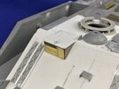
Another bit of good luck there: I had made the basic shape of it from those two bits of brown plastic left over from a kit, and I found that two pieces of photoetch from the Hobby Boss Leopard, and which aren’t even mentioned in the instructions for it, fit perfectly on the front face. I just had to file the pieces flush with the roof and built a top to the sight from plastic card and some more punched bolts.
 

Jakko

Way past the mad part
SMF Supporter
Joined
Apr 28, 2018
Messages
10,958
Points
113
First Name
Jakko

Neil Merryweather

SMF Supporter
Joined
Dec 29, 2018
Messages
4,465
Points
113
Location
London
First Name
Neil
Wonderful scratchery as always,Jakko, and some real inventiveness on display. I marvel at your knowledge of this subject - it is rather off piste. ..
 
Top