MiniArt railway crossing

Jakko

Way past the mad part
SMF Supporter
Joined
Apr 28, 2018
Messages
10,797
Points
113
First Name
Jakko
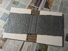
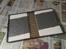
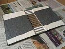
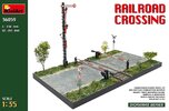
Needing a quick break from the ton of work that is the Landing Craft, Assault model, I opened up the MiniArt railway crossing I purchased not long ago, to build it as a generic base for photographing models on.
MiniArt railway crossing.jpg

I didn’t take photos of the parts in the kit, but basically, you get two vacuum-formed sections of road with verges, a length of railway track (standard gauge, not Russian 1524 mm, despite this kit coming from Ukraine), wooden beams and things to make the actual crossing between the rails, two barriers, a signal post, and two street signs to warn of the crossing. It’s all very well-moulded, though the street sections being vacuum-formed was slightly disappointing — even if I had actually expected them to be :smiling3:

The box says that assembled, it’s 265 × 430 mm, but it’s actually more like 258 × 428 mm. I went to the local hardware store and had them saw me a piece of 5 mm MDF to 26 × 43 cm, to use as a base plate, because you need to provide one yourself — there is no way to assemble the pieces together straight from the box. This set me back all of €1.20, so I was glad I hadn’t bothered to dig deeper around the house for something I could saw to size myself :smiling3:

I first glued the two street plates to the MDF, using thick construction adhesive, which I dabbed into the corners and at a few places along the sides. I didn’t want to try and glue the whole edges down, as that probably would have made a big mess. I simply stuck them almost into the corners, and when the glue was still wet, put a sleeper at either end of the gap down the middle to check the spacing. Once the glue had dried, I measured out the positions for the sleepers so they would be evenly spaced. The instructions don’t say how many you need, but I counted fifteen, so that’s what I went for. It turns out that if you put one sleeper at each end, level with the vacuum-formed parts, you need to put one down every 18 mm — that’s not the space between them, but from left edge to left edge.

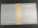
The next day (that is, today), I smeared the whole central part with contact cement and also applied that to the bottoms of the sleepers; after letting it dry for about 15 minutes, I stuck them all on:
IMG_0112.JPG

You may notice I didn’t bother to clean up the sprue attachment points. Doing that would just be unnecessary work, as they will be covered later anyway. I only cleaned them up on the two outward faces.

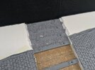
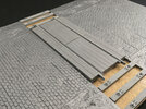
However, having fitted the sleepers, I now have a problem that should have occurred to me earlier. Trying on the rails and the wooden beams between them, what you have is no so much a railway crossing, as a speed bump:
IMG_0113.JPG

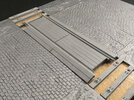
I’m debating what to do. One option is to cut the streets from the base again and raise them up to the level of the crossing. The other is to cut the ends of the beams into a triangle so I can do this:
IMG_0114.JPG

This works because the beams are hollow, so I can just trim the sides so they can fit like this on top of the sleepers rather than between them like in the photo (they’re moved to the side a bit here to illustrate the effect this would have).

I’m not sure how believable the second option is, though — and it would make it hard to display a model on the base, because it would likely end up on the raised bit with a suspension that’s not adapted for it.

A third option would be to cut the road out and raise up only the side at the crossing. However, that causes much the same problem with suspensions …

Anyone have thoughts or ideas on how to do this? I’m leaning to removing the road from the base again and raising the whole thing, but maybe someone has a better idea?
 

stillp

SMF Supporter
Joined
Nov 17, 2016
Messages
7,220
Points
113
Location
Rugby
First Name
Pete
I think I'd rather see the railway lowered than the road raised. You could cut the base each side of the railway, glue a spacer under each of the road sections, then reassemble the whole lot onto another base.
Pete
 

Jim R

SMF Supporter
Joined
Apr 27, 2018
Messages
13,726
Points
113
Location
Shropshire
First Name
Jim
You're right in your thinking about displaying various models that you'll need a level road/rail line. It would be nice if the road sections could be removed without cracking them. You only used blobs of glue so you may be able to use a long thin knife to cut through them. A kitchen knife perhaps.
 

Tim Marlow

Little blokes aficionado
SMF Supporter
Joined
Apr 27, 2018
Messages
16,777
Points
113
Location
Somerset
First Name
Tim
I’d go with Pete’s idea on this Jakko. Anything else could damage the parts.
 

stillp

SMF Supporter
Joined
Nov 17, 2016
Messages
7,220
Points
113
Location
Rugby
First Name
Pete
Easy for me to say as I have a good circular saw bench that I could set to give a 5mm cut and then run the MDF base over it to separate it into 3 parts without damaging any of the plastic bits.. Might be harder without that, but if anyone can do it I'm sure Jakko can.
Pete
 

Jakko

Way past the mad part
SMF Supporter
Joined
Apr 28, 2018
Messages
10,797
Points
113
First Name
Jakko
You could cut the base each side of the railway, glue a spacer under each of the road sections, then reassemble the whole lot onto another base.
That means I end up with three thicknesses of material under the road, and two under the railroad, though … not sure I want to go that route, it will make everything even more thick and heavy.

You're right in your thinking about displaying various models that you'll need a level road/rail line. It would be nice if the road sections could be removed without cracking them. You only used blobs of glue so you may be able to use a long thin knife to cut through them. A kitchen knife perhaps.
I can probably do it with a modelling knife. The blobs are not more than a few centimetres in diameter, and they’re all on the edges.

Having thought about it some more, I’m now thinking the best way to do it might be to cut the road plates off the base, then cut the road out of the plates to leave me with a thin, embossed road section, raise both sides to the required level, and glue the roads straight to that. This will make everything much stronger because you can’t compress the plates anymore, like you can (and do) now when you pick up the base.
 

dave

SMF Supporter
Joined
Nov 16, 2012
Messages
1,918
Points
113
Location
Brussels
First Name
Dave
If you have access to a router you could rout out the wood under the railway so that when inserted the crossing is level with the road bed. A similar effect could be achieved by setting the correct depth of cut on a circular saw, doing each edge carefully then a series of cuts through the rest and remove the waste with a chisel.
 

JayCee

SMF Supporter
Joined
Aug 13, 2019
Messages
1,001
Points
113
First Name
John
I may be completely wrong here, but surely the easiest way would be to remove the sleepers that are underneath the crossing and then it may sit low enough to be almost flush with the road.
John.
 

Andy T

SMF Supporter
Joined
Apr 26, 2021
Messages
1,956
Points
113
Location
Sheffield
First Name
Andy
I thought that at first glance John, but if you did that the rails wouldn't line up with the others sleepers by the look of it.

Unless they were sunk in by routing out the mdf base.

Or maybe cutting off the sides as Jakko has suggested to do with the roadway, just leaving the surface details intact so that they appear sunken.

If that makes any sense :thinking:
 

Jakko

Way past the mad part
SMF Supporter
Joined
Apr 28, 2018
Messages
10,797
Points
113
First Name
Jakko
If you have access to a router you could rout out the wood under the railway so that when inserted the crossing is level with the road bed.
That would definitely be an option if I hadn’t already glued them to the base quite firmly :sad: Though if I hadn’t, it would be a lot less work to build the base with raised sections under the road from the start.
surely the easiest way would be to remove the sleepers that are underneath the crossing and then it may sit low enough to be almost flush with the road.
As Andy also says, the sleepers on both sides of the road would then still be at the height they are now — meaning the rails would have to dip down in the centre, which would be rather unlikely given their strength :smiling3:
 

spanner570

SALAD DODGER
SMF Supporter
Joined
May 26, 2009
Messages
12,988
Points
113
First Name
Ron
The box art shows the section raised above the road level. This is correct. There are plenty of images showing this feature with small ramps butted up. Some wood, some hard rubber. Particularly in rural France.
I hope this is of some use.....

Nerd hat back in cupboard!
 
Last edited:

Jakko

Way past the mad part
SMF Supporter
Joined
Apr 28, 2018
Messages
10,797
Points
113
First Name
Jakko
Forgot to mention that, yes: when I noticed the problem, I took another look at the box art and found that it doesn’t quite match up with what you can build straight from the box … If only MiniArt had moulded the road sections 4 mm deeper, the whole problem wouldn’t have been there in the first place. A bit thicker plastic would also not have gone amiss :smiling3:
 
  • Like
Reactions: JR

Jakko

Way past the mad part
SMF Supporter
Joined
Apr 28, 2018
Messages
10,797
Points
113
First Name
Jakko
For once, something turned out to be a lot easier than I thought it was going to be!

IMG_0117.jpeg

First, I sliced through the glue dots easily with my modelling knife and could take the street panels back off the base. Then, I found the glue stuck well enough to keep the panels on the MDF for diorama purposes, but still poorly enough that I could just pull/roll the glue cleanly off both materials. Finally something that goes my way :smiling3:

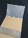
I had measured the sleepers plus crossing to be about 9 mm thick, so to raise the terrain, I got out some sheets of foam board, about 3 mm and 5 mm thick, and cut two pieces out of each. Then I smeared both halves of the base with contact cement, as well as one side of two pieces of foam board. After leaving the glue to dry for about half an hour, I stuck the board to the base, smoothed it down (the board was curved because when I bought it 10+ years ago, I had to carry it through the rain for a bit :sad: ) and stacked a pile of books on each for another half an hour or so :smiling3:

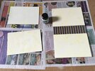
Then, more contact cement:

IMG_0119.jpeg

The bottle in the middle is the cement. It comes with a brush in the lid, so it’s easy enough to apply, but beware of getting strings of it everywhere.

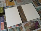
And when that had dried for half an hour or so too, I repeated the pressing-down, stacks of books, etc. to end up with:

IMG_0120.jpeg

I did make a slight mistake, in that I had wanted to put the 3 mm sheets at the bottom, mainly because that would make it easier to locate the top sheet against the sleepers, which are about 5 mm thick. Not paying attention, though, the first piece of board I smeared glue onto, was a 5 mm one. Oh, well. Also, the damage on the edge of the left sheet is because I accidentally trod on it — I did this glueing on the attic floor, where there’s enough room and it doesn’t really matter if a drop of glue goes somewhere it shouldn’t. Still, as you can see, I laid down some newspaper first to prevent this.

Now I’m going to trim the edges of the board to be level with the MDF, then cut the edges off the street panels and stick them down with contact cement too.
 

Jakko

Way past the mad part
SMF Supporter
Joined
Apr 28, 2018
Messages
10,797
Points
113
First Name
Jakko
The original idea had been to just cut the edges off the kit’s street plates so I could glue them to the foam board, but I changed that to cutting the streets out of the plates instead. That way, I could put them at a slight angle by cutting a small bit off one end, and and glueing it back at the other:

IMG_0123.jpeg

In retrospect, I should have cut it further towards the middle, to create two larger panels that are easier to stick down. Still, I now have a slightly more interesting scene, with not everything at right angles to the base. IMHO, MiniArt would have done better to do that too, since it would still allow them to mould a single street piece twice. (The rails and crossing are still loose here.)

I also cut the edges of the foam board leading down to the track, so the groundwork later on will slope to it a bit as well.

Next, I added edging to the base:

IMG_0124.jpeg

This is black plastic, fake veneer that is supposed to be ironed on, but I stuck it down with more contact cement because I didn’t really trust the iron-on glue to work well with the 5 mm or so thickness of MDF. Then I just trimmed the edging once the glue had dried:

IMG_0125.jpeg

I’ve tried to leave it a little bit sticking up above the foam board, to give a natural edge for the filler to go against, when I use that to make the verges later on. First, I need to add balast to the track, but only for the six gaps into which I glued bits of 3 mm foam board — all the others will be hidden by the crossing itself. TBH, I wasted a ton of sleepers there too, as they will be completely out of sight. Just sticking two or three there would have been enough to support everything.
 
Last edited:

Jakko

Way past the mad part
SMF Supporter
Joined
Apr 28, 2018
Messages
10,797
Points
113
First Name
Jakko
Track ballast added:

IMG_0126.jpeg

This is model railway stuff that I bought so long ago I don’t even remember it, poured from its bag over a thick layer of PVA glue spread all over the bits of foam board between the sleepers. Once the glue had dried, I shook off the loose bits (into a box lid, so I could put them back into the bag) and test-fit the rails so I could cut away everything that was in their way. Then I painted thinned PVA over everything to make sure it all stays stuck down, as well as fill some of the gaps that were somehow left with the bits that came loose because of the brush.

As I don’t like wasting things, I also took some pliers to the sleepers in the middle:

IMG_0127.jpeg

A bit of careful pushing and pulling, and I had four of them out that wouldn’t be seen anyway once the base is complete :smiling3: I could probably have removed all except maybe the one in the middle (that is out here) and it would still have been nice and level, but I didn’t want to run the risk of the crossing sagging too much.
 

Jakko

Way past the mad part
SMF Supporter
Joined
Apr 28, 2018
Messages
10,797
Points
113
First Name
Jakko
I’ve started adding wall filler to add some texture to the verges, but when it’s wet it doesn’t stick much at all to the smooth card of the foam board, even after I cut a crosshatch pattern in it with my knife. It being 30° in my hobby room (and 28+ outside) also doesn’t encourage me to finish this job just now :sad:
 

Tim Marlow

Little blokes aficionado
SMF Supporter
Joined
Apr 27, 2018
Messages
16,777
Points
113
Location
Somerset
First Name
Tim
I’ve started adding wall filler to add some texture to the verges, but when it’s wet it doesn’t stick much at all to the smooth card of the foam board, even after I cut a crosshatch pattern in it with my knife. It being 30° in my hobby room (and 28+ outside) also doesn’t encourage me to finish this job just now :sad:
Paint it with PVA first Jakko. It’s what plasterers do when they need better adhesion to the walls…..
 

Jakko

Way past the mad part
SMF Supporter
Joined
Apr 28, 2018
Messages
10,797
Points
113
First Name
Jakko
Good idea, thanks :smiling3: Leave the PVA to dry first, or apply the filler while it’s still wet?
 

Andy T

SMF Supporter
Joined
Apr 26, 2021
Messages
1,956
Points
113
Location
Sheffield
First Name
Andy
Good idea, thanks :smiling3: Leave the PVA to dry first, or apply the filler while it’s still wet?
I've used pva with a sprinkle of fine sand in the past to give a grippy surface for filler.

I prefer to let it dry quite well just in case it causes cracking of the filler later when the pva dries and shrinks, but I've seen others go straight over as soon as its tacky (which won't take long in the heat you're working in!)
 
Top