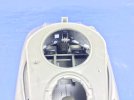
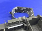
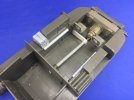
US Army M32B1 Tank Recovery Vehicle

Jim R

SMF Supporter
Joined
Apr 27, 2018
Messages
13,867
Points
113
Location
Shropshire
First Name
Jim
Hi Jakko
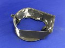
That superstructure looks very awkward to line up but you seem to have got it done
it’s very thin, maybe half a millimetre or so.
I suppose trying for scale thickness results in fragile parts. The sides should give it a bit more strength.
Jim
 

adt70hk

I know its a bit sad but I like quickbuild kits!!!
SMF Supporter
Joined
Sep 4, 2019
Messages
9,526
Points
113
First Name
Andrew
Nice start Jakko. But rather you than me on those tracks!

ATB.

Andrew
 

Jakko

Way past the mad part
SMF Supporter
Joined
Apr 28, 2018
Messages
10,976
Points
113
First Name
Jakko
That superstructure looks very awkward to line up but you seem to have got it done
What I should have done was scrape the inside of the ring a little larger, because getting three of the four parts (front, two sides and rear) in was easy enough, but trying to add the fourth required me to almost force things.

I suppose trying for scale thickness results in fragile parts.
I must say I’m slightly puzzled why it’s a separate part at all. The hull top is a piece they made specifically for the M32B1 kit, with a flap at the front for the winch, the mortar mount moulded on, and holes for the locating pins of this ring in the top. Since the ring of the superstructure sits directly on the roof and was bolted down on the real tank, the only purpose it has being separate, is that you could build an M32 with its superstructure removed … but if you do, you will need to fill its locating holes anyway. In short: why didn’t they mould the ring integrally with the hull top?

Anyway, it’s together now so all I need to do is fill the gaps and add missing detail, mainly stowage and straps on the inside :smiling3:

rather you than me on those tracks!
Yeah, that’s kind of the feeling I have too. I console myself with the thought that at least they’re not Model Kasten ;)
 

adt70hk

I know its a bit sad but I like quickbuild kits!!!
SMF Supporter
Joined
Sep 4, 2019
Messages
9,526
Points
113
First Name
Andrew
What I should have done was scrape the inside of the ring a little larger, because getting three of the four parts (front, two sides and rear) in was easy enough, but trying to add the fourth required me to almost force things.


I must say I’m slightly puzzled why it’s a separate part at all. The hull top is a piece they made specifically for the M32B1 kit, with a flap at the front for the winch, the mortar mount moulded on, and holes for the locating pins of this ring in the top. Since the ring of the superstructure sits directly on the roof and was bolted down on the real tank, the only purpose it has being separate, is that you could build an M32 with its superstructure removed … but if you do, you will need to fill its locating holes anyway. In short: why didn’t they mould the ring integrally with the hull top?

Anyway, it’s together now so all I need to do is fill the gaps and add missing detail, mainly stowage and straps on the inside :smiling3:


Yeah, that}s kind of the feeling I have too. I console myself with the thought that at least they’re not Model Kasten ;)
I see what you mean!! 9 parts per link...... That's half the number of pieces for an entire Armourfast Panther!! Good luck!
 

Jakko

Way past the mad part
SMF Supporter
Joined
Apr 28, 2018
Messages
10,976
Points
113
First Name
Jakko
I tried finding instructions for them, because I kind of want to know what those nine parts are, but had no luck so far.
 

CarolsHusband

SMF Supporter
Joined
Feb 9, 2021
Messages
430
Points
93
Location
Sunny Cornwall
First Name
Dan
Of course you can — you don’t need to ask permission, as far as I’m concerned :smiling3:

I might have to revisit this for a bit of a refresh ( and a dust). I do remember it being a fun project.

ou9m7n1.jpg
 

Jakko

Way past the mad part
SMF Supporter
Joined
Apr 28, 2018
Messages
10,976
Points
113
First Name
Jakko
It’s a little dusty, but there seems to be a pretty decent model lurking underneath that :smiling3:
 

Jakko

Way past the mad part
SMF Supporter
Joined
Apr 28, 2018
Messages
10,976
Points
113
First Name
Jakko
Puttied and sanded:

28F6A0C1-0183-4367-BA9B-8BD6AD26B266.jpeg

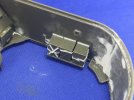
On the left-hand side is a rack for three 50-round ammo boxes for the .50-calibre machine gun, but the boxes themselves can use some detail as well as straps:

D3495FE6-787F-4F1A-9E3E-0AECEC2A8260.jpeg

The kit includes two with crosses stamped in, and two without, but the former only have a cross on one side when it should be on all of them (or the visible ones at least :smiling3:) so I added more from 0.5 mm plastic rod that I scraped into half-round rod. The bits of plastic strip at the top are also part of the lid, and were missed by Tasca, as were the retaining straps (paper-thin plastic card). They still need some small tabs added to the lids, though :smiling3:

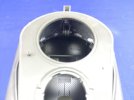
Now I have the superstructure together, I discovered a problem, though:

705DFC3C-BD72-4056-A333-2F6D9EE97084.jpeg

You can see all the way to the vehicle’s nose through the opening in the roof, and it’s very obvious there is no driver’s compartment. After mulling it over for a while, I decided to buy another M10 tank destroyer kit and pinch its parts for this area … I mean, it’s either get one of those for about 30 euros or spend at least that much, if not more, for a resin set. And in the first case, I’ll have another vehicle I can build if I just keep the front hatches closed :smiling3:
 

Airborne01

SMF Supporter
Joined
Mar 30, 2021
Messages
3,233
Points
113
Location
Essex
First Name
Steve
Puttied and sanded:

View attachment 453688

On the left-hand side is a rack for three 50-round ammo boxes for the .50-calibre machine gun, but the boxes themselves can use some detail as well as straps:

View attachment 453689

The kit includes two with crosses stamped in, and two without, but the former only have a cross on one side when it should be on all of them (or the visible ones at least :smiling3:) so I added more from 0.5 mm plastic rod that I scraped into half-round rod. The bits of plastic strip at the top are also part of the lid, and were missed by Tasca, as were the retaining straps (paper-thin plastic card). They still need some small tabs added to the lids, though :smiling3:

Now I have the superstructure together, I discovered a problem, though:

View attachment 453690

You can see all the way to the vehicle’s nose through the opening in the roof, and it’s very obvious there is no driver’s compartment. After mulling it over for a while, I decided to buy another M10 tank destroyer kit and pinch its parts for this area … I mean, it’s either get one of those for about 30 euros or spend at least that much, if not more, for a resin set. And in the first case, I’ll have another vehicle I can build if I just keep the front hatches closed :smiling3:
Onwards and upwards! :upside:
Steve
 

JR

Member of the Rabble and Pyromania Consultant
SMF Supporter
Joined
May 26, 2015
Messages
17,393
Points
113
Location
lincs
First Name
John
Very much to your normal posting about the actual vehicle, most enjoyable to read.
Should be well worth following. Seat at front please .
 

Jakko

Way past the mad part
SMF Supporter
Joined
Apr 28, 2018
Messages
10,976
Points
113
First Name
Jakko
Now with that here, I think it’s time for a bit more history of the kind that several of you appear to enjoy reading :smiling3:

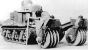
Like others, the US Army recognised the need for vehicles to clear mines quickly during an attack. Where the British mainly tried rollers, ploughs, explosive line charges and flails, then mostly settled on the latter, the Americans mainly worked on rollers, in addition to keeping an eye on British developments and also trying all kinds of oddball things, including an adaptation of naval Hedgehog anti-submarine mortars and even a bunch of heavy-duty pistons that would pound the ground in front of the tank. Most successful of all these, though, seemed to be very heavy rollers. The first serious attempt was the Mine Exploder T1:
Mine Exploder T1.jpg

This consisted of rollers made up of several large, heavy steel discs. Two rollers were mounted on the front of the M3 medium tank, and a third was towed behind it. It was soon improved by moving the third roller to the front, probably so that there was no risk of any mines ending up under the tank, and so became the T1E1.* However, that put a lot of weight on the front, so it was decided to use it with the M32 tank recovery vehicle instead, because it was envisioned that it could use its crane to take some of the weight, and the crane also came in handy for fitting and removing the rollers from the vehicle. The combination looked like this:
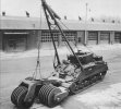
Mine Exploder T1E1.jpg

This had rollers made up of discs 122 cm in diameter, 5 cm thick and weighing some 580 kg each, resulting in a complete roller that weighed around 16 tonnes; it could clear a path about 3 metres wide. The combination appeared to work well enough, so 75 of them were produced in April of 1944 and most of them shipped to Europe. Units to use them were only formed in September that year, though, when 738 and 739 Tank Battalions (Special) were converted from Shop Tractors to Mine Exploder tanks. Each was to have 18 T1E1s, 24 T1E3s, 12 tank dozers, and 18 Shermans with 76 mm guns, but in practice were also assigned some British-supplied Sherman Crabs, and even a few Sherman DD (amphibious) tanks for the crossing of the Rhine in 1945.

The T1E2 had larger but thinner rollers than the T1E1, was also used on the M32, but not produced beyond prototypes. The T1E3 did go into production; it had even larger rollers than the T1E1, and was mounted on a regular Sherman tank. To improve mobility, the rollers were powered by means of a chain driven by the tank’s drive sprocket:
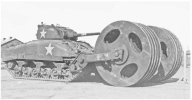
Mine Exploder T1E3.jpg

Under actual battlefield conditions, though, all of these tanks were very slow and bogged down extremely quickly in soft ground, like here:
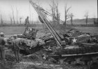
Bogged-down T1E3.jpg

On the left is a T1E3 that was clearing mines on a road on 19 December 1944; when some mines detonated, they blew out part of the road and caused the tank to slide into the ditch along the side of the road and it got very stuck. You can see the rollers have been detached from the tank to aid in its recovery, for which two M32B1s are used. Both of those M32B1s have a large horizontal bar with big eyes on the hull front, indicating that they are actually also mine exploders: that bar is where the T1E1 equipment attaches.

Oh, and since we’re discussing US Army experimental mine exploders here, I can’t really not mention this one:
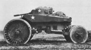
Mine Exploder T10.jpg

This is the mine exploder T10, which was an M4A2 Sherman tank with the front corners of the hull cut away so that 244 cm diameter rollers could be fitted, driven from the normal transmission, and a 183 cm one at the rear. This was not considered a success, oddly enough :smiling3:

* And here’s an aside on US Army equipment designations thrown in for free :smiling3: Since the late 1920s, equipment was principally designated by a short description of its function, followed by an M-number that started at 1 for every class of equipment. Thus, there was an M1 rifle, an M1 carbine, an M1 helmet, an M1 combat car (read: “light tank for the Cavalry”), and so on. There never really was an M1 medium tank, but there were M2, M3 and M4 medium tanks. Variants were indicated with an A after the number, followed by a sequential number to indicate the variant: M1 is the basic version of the thing, M1A1 is the first variant, M1A2 is the second, etc. (In the early 1940s, it was realised that this was confusing, so sequential numbering was mostly dropped. This is why there are light tanks M3 and M5, but not a light tank M4 — that was to have been the designation, but expected confusion with the medium tank M4 resulted in it being called the M5 instead.)

When there was some kind of substitution made for manufacturing purposes, but which made no functional difference to the item’s operation, a B-number was assigned. Thus, the M1 is a thing, the M1B1 is the same thing but with — for example — a part that was made in aluminium now being made in steel, or wood substituted for plastic, or something like that. This is why the model I’m building is an M32B1: the M32 uses the hull of the M4 medium tank, while the M32B1 is functionally identical but uses the hull of the M4A1.**

Now, T-numbers indicate prototypes; once it was standardised for service, it got an M-number instead, and often not the same as the T-number. For example, the Tank Recovery Vehicle T5 became the Tank Recovery Vehicle M32 upon standardisation. Similarly, variants or alternate designs of prototype items get an E-number instead of an A-number: the mine exploder T1 was the first roller device, the T1E1 was the second, T1E2 third, etc.

** If you’re following along, you may now realise that the Sherman’s designations break the rules. The principal difference between the M4 and M4A1 is how the hull is constructed, while that between M4, M4A2, M4A3, M4A4 and M4A6 is the engine. Neither of these affects the tank’s basic functionality, so they should have been M4, M4B1, M4B2, etc. Oddly, this logic was followed for the M32 TRV.
 

Jakko

Way past the mad part
SMF Supporter
Joined
Apr 28, 2018
Messages
10,976
Points
113
First Name
Jakko
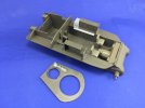
As usual, work is going slowly because I have to try and work out all kinds of details that are missing, from not enough information. A stroke of luck is that someone sent me a scan of the technical manual for this vehicle after I asked some questions about it on Missing-Lynx, which has filled in at least some of the gaps. As for actual building, I added a basic driver’s compartment from the AFV Club 17-pounder M10 kit I bought the other day:

7DF0D811-6308-4C74-9CA2-101BD2601CD7.jpeg

That’s the lighter green parts, for those wondering :smiling3: In the left sponson, I added two water jerry cans, made from Italeri cans with lids from a Rye Field Model Sherman, whose actual cans were not as good but the Italeri jerrycan set only includes fuel-can lids, not those for the water cans. The opposite sponson needs to be filled with 81 mm mortar ammo packing tubes, but Tasca doesn’t provide enough, and in any case those are too long and won’t fit. I need to find some material of about 2.5 mm diameter that I can cut into enough packing tubes for both here and inside the superstructure.

On the inside of the roof, I added a Tamiya M1 Thompson submachine gun, because it’s sort of visible through the hatch. The plastic below it is because on the real vehicle, there was a rack for magazines for the weapon there, and the gun was strapped to the underside of that. As the rack itself is out of sight, it doesn’t need more detail that this, but bits of the gun can just be seen. (The Tamiya weapon is not well-detailed, but it’s clunkier than the better alternatives I have, and that’s more important here than it being a perfect replica :smiling3:)

Here’s a comparison shot with earlier, which shows well how obvious the lack of interior for the driver’s compartment is:

2D85FD2B-297C-4173-A194-A42380344F83.jpeg

It needs more stuff added, mainly the drive shaft, but these few parts fill a huge hole in the model.
 
Last edited:

Jim R

SMF Supporter
Joined
Apr 27, 2018
Messages
13,867
Points
113
Location
Shropshire
First Name
Jim
Hi Jakko
Thank for the historical background. I'm one who finds it interesting. That "earthworm" aftermarket stuff should make this a very unusual model. I've never heard of BoldDivision. You're making good progress, understandably slow with the research and scratching parts.
Jim
 

stillp

SMF Supporter
Joined
Nov 17, 2016
Messages
7,240
Points
113
Location
Rugby
First Name
Pete
I need to find some material of about 2.5 mm diameter that I can cut into enough packing tubes for both here and inside the superstructure.
Cotton bud (Q-tip) shafts?
Pete
 
  • Like
Reactions: JR

Jakko

Way past the mad part
SMF Supporter
Joined
Apr 28, 2018
Messages
10,976
Points
113
First Name
Jakko
Thank for the historical background. I'm one who finds it interesting.
Cool, I’m clearly not writing it for nothing, then :smiling3:

That "earthworm" aftermarket stuff should make this a very unusual model.
Also a very big model … Especially since I intend to have the boom up.

I've never heard of BoldDivision.
Neither had I until a few months ago, when someone wrote an article about some of their products in the magazine of a club I’m in. I checked out their site and found it’s mostly “Wehrmacht 1946”-what-if, which is interesting but not something I feel a need to build (right now, anyway :smiling3:) but also some real-world things you don’t find anywhere else AFAIK — like this T1E1.

You're making good progress, understandably slow with the research and scratching parts.
I find it odd that Tasca included a good deal of the interior, but missed out things that are just as visible. Finding out what’s supposed to be there, and finding parts to make it from, are a good deal of work. For example, I need to find at least five water bottles (the kind American soldiers wore on their belts), but have only scrounged up two so far …

Cotton bud (Q-tip) shafts?
Oh, good idea, I hadn’t thought of that yet. I’ll need to go look round the house if there are any and take some callipers to them :smiling3:
 

Jakko

Way past the mad part
SMF Supporter
Joined
Apr 28, 2018
Messages
10,976
Points
113
First Name
Jakko
For the mortar round tubes, I did more research and found dimensions: in 1:35 scale, they should be about 16.3 mm long and 2.8 mm diameter. I looked at cotton buds, as suggested by Peter, but the ones I had were far too small in diameter. By a stroke of luck, though, the turret sprue (H) has runners 2.8 mm diameter :smiling3: So I cut it into pieces with clippers, scraped off the thin mould lines and then used my RP Toolz guillotine to cut it into thirty, 16 mm lengths.

I put eleven into the turret, with bits of plastic strip to replicate the spacers of the real thing; it still needs a strap that goes over the tubes, though. The other nineteen are in the hull:

1C5BB897-832C-49D9-94D1-8AE0BDDC108B.jpeg

If these had been parts I had purchased, I wouldn’t have put nineteen in but only as many as needed to give the impression of a full hull rack. However, this is sprue, so … :smiling3:

In the lower hull, I then added a drive shaft and the cover over the chain that drives the winch:

FA6EC00E-A7FC-4F6C-BB2D-76E3AF5639A1.jpeg

This isn’t meant to be totally accurate, but mainly to give the impression that the stuff that should be there, actually is. The bit between the chain cover and the transmission is just a piece of something that I found on my workbench, but which serves nicely to fill the otherwise very obvious gap between the drive shaft and the transmission.
 
Last edited:
Top