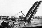
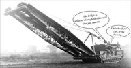
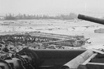
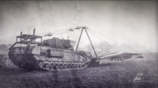
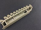
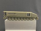
Churchill Mk. IV AVRE with Small Box Girder Assault Bridge Mk. II

Jakko

Way past the mad part
SMF Supporter
Joined
Apr 28, 2018
Messages
10,889
Points
113
First Name
Jakko
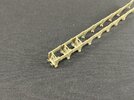
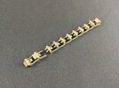
The bridge itself is now just about done:
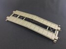
FCAC47E9-4917-4C12-931C-A4EA52E97137.jpeg

To attach the decks, it works best if you put them on the girders a few centimetres away from the bridge’s centre, because the girders there are a bit too thick for the deck pieces to fit over them easily. Then just slide up to the middle and run glue into the joints.

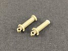
There are some kind of grips/levers/thingies on the bridge, four to each deck, but one had gone missing from a sprue, so I had to fabricate a replacement:
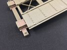
AA134C74-DCF6-4E9D-997D-EAAF6BDACBA3.jpeg

This is just two 1.6 mm discs punched out of 0.25 mm plastic card, with the top disc having its centre cut away so that there’s a groove down the middle. The handle itself is a piece of stretched plastic rod (like sprue, except I had reason to stretch some plastic rod the other day to obtain a cone, so I used the thin bit I had left over for this).

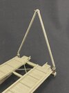
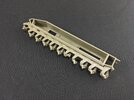
At the “tank end” of the bridge are two pedestals for the booms by which the bridge was winched up:
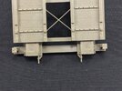
73546DE6-364B-4D52-921C-4866EA6928C6.jpeg

The holes in them are for hinges for the booms, so they will fall away from the bridge deck when it’s laid.

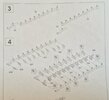
However, AFV Club made a pretty major mistake here. Take a look at the instructions:
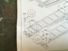
F59BDD41-3113-489E-9165-0F50D37D75EF.jpeg

Both of them are labelled as part U17, and the instructions clearly point out which way the holes should face. Unfortunately, you can’t make it like that because if you turn U17 through 90 degrees it won’t fit, and if you cut off its locating pin so you can turn it, it will still be wrong (the top plate is not square and the angle of the holes would be incorrect).

I solved this by cutting off the top, filing everything square and flat, adding some plastic card, and re-attaching the top upside-down:
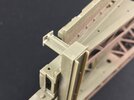
9DEE6F59-5657-44EA-A36D-8522D2BE0043.jpeg

… and when writing this, of course, I discovered that the fix is far simpler … use part U6 :sleeping: So the instructions are wrong, the right part is on the sprue, but I had overlooked it because they’re a little confusing. Anyway, I’ll keep what I have, as it fits fine.
 

tr1ckey66

SMF Supporter
Joined
Mar 6, 2009
Messages
3,686
Points
113
First Name
Paul
Good progress Jakko. It’s reading builds like yours that help others with errors in instructions. I think this bridge laying Churchill is another kit I’m going to have to add to the stash after I get the Bobbin tank.

BTW, the CDL Grant turned out great
 

Jakko

Way past the mad part
SMF Supporter
Joined
Apr 28, 2018
Messages
10,889
Points
113
First Name
Jakko
Good fix on part U17 even if you didn't need a fix. :rolling:
In the end I did pull it off to replace it by U6, because I discovered that these pedestals lean to one side slightly, and my converted U17 leaned the wrong way. Only by a degree or two, at a guess, but enough to be noticeable.

It’s reading builds like yours that help others with errors in instructions.
I see it as my civic duty to point out these kinds of things ;)

I think this bridge laying Churchill is another kit I’m going to have to add to the stash after I get the Bobbin tank.
[/quote]
I want to build a fascine carrier — that was what I had in mind to do first, until AFV Club announced this one.

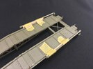
BTW, the CDL Grant turned out great
It’s not finished yet! :smiling3: Though it won’t be very much longer …
 

tr1ckey66

SMF Supporter
Joined
Mar 6, 2009
Messages
3,686
Points
113
First Name
Paul
I want to build a fascine carrier — that was what I had in mind to do first, until AFV Club announced this one.
I think you’re pretty much like me Jakko. I’d like to build a set of ‘funnies’ - Bridgelayer, fascine, AVRE, Bobbin. I built a Sherman Crab a while ago from the Dragon M4A4 and the Resicast conversion and I also have the Resicast DD M4A1 (lowered skirt).
So many plans and never enough time :rolling:

In the meantime your bridgelayer is coming along nicely.
I follow with interest :thumb2:
 

Jakko

Way past the mad part
SMF Supporter
Joined
Apr 28, 2018
Messages
10,889
Points
113
First Name
Jakko
For me, this particular set of funnies is mainly because they’re of local interest, as explained earlier in this thread. For that reason, I almost bought a Resicast DD a few weeks ago when I was at a model show in Belgium, where Resicast was present too, but just under €200 for a model I won’t be building any time soon … not yet :smiling3:
 

Jakko

Way past the mad part
SMF Supporter
Joined
Apr 28, 2018
Messages
10,889
Points
113
First Name
Jakko
The booms by which the bridge was lifted up are now also on it:

DF63422D-DC3B-40BC-81A3-B50E675831F8.jpeg

Which completes this part of the build, except for adding the cables and their connectors, of course, that run from the top of each boom to the eyes at the far end of the bridge. I already made up the cables, but decided not to fit them yet, because that can also easily be done after painting, and that means they won’t get in the way for that.

The instructions are slightly odd again here. They indicate to use part U31 for both the booms, but the sprues have two booms each: U31 and U29. However, I couldn’t find a difference between them, nor between hinges U23 and U24, so I think it doesn’t really matter which you use, or on what side.

Similarly, the instructions tell you to use parts from O sprue for the cable eyes, the D-clasps and their pins, but all of those are also on U sprue (as parts 26, 30 and 25, respectively).

The booms are still movable here, because I don’t want to risk knocking them off with my usual clumsiness, and they’re rather loose in their hinges anyway. For that reason, I decided to protect them:

E657E1C2-52DD-400A-910F-514808C1F809.jpeg

Just a piece of balsa strip and some tape on each side, because when the booms lie down, they hang sort of in the void next to the bridge deck.

On to the tank … soon :smiling3:
 
Last edited:

Jakko

Way past the mad part
SMF Supporter
Joined
Apr 28, 2018
Messages
10,889
Points
113
First Name
Jakko
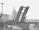
Here’s a tip for everyone who also wants to build a replica of a real vehicle: look closely at photos before you begin building …

AVRE A2A bridge while in LCT 737.jpeg

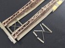
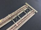
I had put the crosspieces in per the instructions, so one at the tank end and two as far forward as possible. But as you can see in the photo above, on the real one that I’m building (so not necessarily on all SBG bridges), there was one fully forward and one just in front of the centreline (the third one is hidden by the landing craft). So, more work demolishing stuff:

IMG_9527.jpeg

Luckily, the kit provides four of these crosspieces, so I had one spare to put into the correct position:

IMG_9528.jpeg

This did require cutting off small sections of the U-beam, because else it wouldn’t fit due to the tabs on the girders.
 
Last edited:

Scratchbuilder

SMF Supporter
Joined
Jul 2, 2022
Messages
1,987
Points
113
Location
Luton
First Name
Mike
Jakko, keep going, it's all coming together. Just make sure the single cross piece is at the vehicle end as the big gap was so that the commanders view was not obstructed. But in contradiction on page 35 of 'Vanguard of Victory' by David Fletcher, it cleary shows a photo of an SBG loading at Westward Ho beach where all of the centre section of the bridge has planks all the way across with just a small part closest to the vehicle left open.... But I would assume that later they were removed as being more of a hindrance than a help.
Mike
 

Jakko

Way past the mad part
SMF Supporter
Joined
Apr 28, 2018
Messages
10,889
Points
113
First Name
Jakko
I’ve noticed a fair amount of variation in the bridges, not only in the locations of the crosspieces but also the direction of the diagonal bracing in the girders. Of course, the girders could be put into the bridge either way up, though it so far looks like the right and left halves usually had them in the same direction even if front and rear sometimes weren’t. For example:

49CCE9FB-0CFD-4613-B7BB-24E340571618.jpeg802A0EAA-BF1A-4359-A021-BAE2AD95DDD2.jpegBridge A2A.jpg

Notice that the first photo has the bracing going /\/\/\|/\/\/\ while in the second photo, it runs \/\/\/|\/\/\/, and in the third (which is the actual bridge my subject carried), it goes /\/\/\|\/\/\/. The crosspieces in the first photo are at positions 1, 2 and 6 (counting from the front) while the second one seems to have a crosspiece in all six positions, and (as shown earlier) my subject has them at 1, 3 and 6.

The short of it is that if you’re just building a generic model then pretty much any will do, but if you’re building a model of a specific tank then you’ll need to pay attention.

That second photo, BTW, has me puzzled over how to articulate the suspension. It shows it very nicely, but I haven’t worked out yet how roadwheel No. 8 can be further extended than Nos. 9 and 10 if 8 is on the ground but 9 and 10 aren’t. This seems to imply 8 (and a few in front of it) have extended downward, which would be logical due to the spring pushing it that way when the weight of the bridge tips the tank forward, but then why aren’t 9 and 10 also pushed down?

I’ll have to do some measuring in a photo of a Churchill without a bridge on level ground to work out the ratio of wheel diameter to wheel deflection in “neutral” and also for the tank with the bridge, so I can figure out by how far to compress/extend each wheel arm.
 

Scratchbuilder

SMF Supporter
Joined
Jul 2, 2022
Messages
1,987
Points
113
Location
Luton
First Name
Mike
I’ve noticed a fair amount of variation in the bridges, not only in the locations of the crosspieces but also the direction of the diagonal bracing in the girders. Of course, the girders could be put into the bridge either way up, though it so far looks like the right and left halves usually had them in the same direction even if front and rear sometimes weren’t. For example:

View attachment 477536View attachment 477537View attachment 477538

Notice that the first photo has the bracing going /\/\/\|/\/\/\ while in the second photo, it runs \/\/\/|\/\/\/, and in the third (which is the actual bridge my subject carried), it goes /\/\/\|\/\/\/. The crosspieces in the first photo are at positions 1, 2 and 6 (counting from the front) while the second one seems to have a crosspiece in all six positions, and (as shown earlier) my subject has them at 1, 3 and 6.

The short of it is that if you’re just building a generic model then pretty much any will do, but if you’re building a model of a specific tank then you’ll need to pay attention.

That second photo, BTW, has me puzzled over how to articulate the suspension. It shows it very nicely, but I haven’t worked out yet how roadwheel No. 8 can be further extended than Nos. 9 and 10 if 8 is on the ground but 9 and 10 aren’t. This seems to imply 8 (and a few in front of it) have extended downward, which would be logical due to the spring pushing it that way when the weight of the bridge tips the tank forward, but then why aren’t 9 and 10 also pushed down?

I’ll have to do some measuring in a photo of a Churchill without a bridge on level ground to work out the ratio of wheel diameter to wheel deflection in “neutral” and also for the tank with the bridge, so I can figure out by how far to compress/extend each wheel arm.
Correct Jakko,
I think it was how and where they were constructed and the interpretation of the design drawings, the Resicast bridge has the diagonals all going in the same direction as per the bottom photo.
As for the suspension, I can only say is to cut one ring from the springs of the first four suspension units on each side. This will take the tension of the plastic inner spring and as these are moveable will allow the model to gain a nose down attitude, or you could glue the plastic inner springs in place, but then you have the problem of lining up the wheels. And once the bridge is attached then the weight should help with the nose down attitude. As can be seen in the pic, the last two wheels are almost floating clear of the ground.
Mike
 

Andy the Sheep

SMF Supporter
Joined
Apr 7, 2019
Messages
1,551
Points
113
Location
North Eastern Italy
First Name
Andrea
View attachment 477537

That second photo, BTW, has me puzzled over how to articulate the suspension. It shows it very nicely, but I haven’t worked out yet how roadwheel No. 8 can be further extended than Nos. 9 and 10 if 8 is on the ground but 9 and 10 aren’t. This seems to imply 8 (and a few in front of it) have extended downward, which would be logical due to the spring pushing it that way when the weight of the bridge tips the tank forward, but then why aren’t 9 and 10 also pushed down?
Jakko, my educated guess is that wheels # 9 and 10 sit higher then #8 because it seems they meet the track before they can reach the full extended position.
 

Jakko

Way past the mad part
SMF Supporter
Joined
Apr 28, 2018
Messages
10,889
Points
113
First Name
Jakko
I think it was how and where they were constructed and the interpretation of the design drawings, the Resicast bridge has the diagonals all going in the same direction as per the bottom photo.
I’ve not seen that one in person, I wondered whether to buy it or the IMA kit, and decided on the latter eventually. Should have waited a few months longer :smiling3:

As for the suspension
What I’m going to do is put spacers on the inside, to push the stems upwards and compress the springs. The problem with this is working out by how much, but I’ve got that figured out by now, which I’ll explain in detail in a later post, when I get to the point where I will actually build it :smiling3:

Jakko, my educated guess is that wheels # 9 and 10 sit higher then #8 because it seems they meet the track before they can reach the full extended position.
When working out the deflection as I mentioned above, the conclusion I reached is that Nos. 9 and 10 have limiters that prevent them extending as far as the wheels forward of them. This photo shows it well:

8B20DAA9-2F7E-499A-9417-988340120E69.png

Wheel No. 9 isn’t even resting on the track, so something must be preventing it from going down any further, while No. 8 is clearly extended further down.

However, as I said I’ll get back to that later. In order to work out how far to pad/extend the suspension, I need to put on the wheel arms first, and that means putting it together. AFV Club would have you build it like this:

C5C40F3C-94B7-4272-8812-0F33648A1368.jpeg

That is, first put the strips of pivot points together for each side (the frontmost two are a separate part because the kit includes two different types), then glue the transverse plates to one side, and add the other side while trapping the wheel arms between them. I don’t think I could keep eleven loose suspension arms in place while I glue the second side strip on, though, so I worked out an easier way.

First of all, I kept the short and long strips separate, because I don’t see the point of adding them together already. Then, add a plate to one end of a strip:

107DC7CB-A488-4F96-A195-5E497132DC1C.jpeg

Next, put a wheel arm on there as well:

1D4F230B-105B-4F6A-B8C0-E6D2E13DA759.jpeg

And glue the second strip on:

DB305F8E-34A0-4977-AE8C-1487324B60E8.jpeg

Be sure to not get any glue on the wheel arm!

Then, add a wheel arm to the second station:

5613F19C-4BA3-4E81-9A11-8B9D796369FE.jpeg

Insert the plate for the second station from the top:

84224769-605B-494A-AE8E-694E36326153.jpeg

From the other side:

2BCC3719-AF70-45FA-834B-44C89CC3B5A7.jpeg

Glue it in place by letting some liquid cement flow into the joints from above, again taking care to keep the arm loose.

Repeat for the third arm and plate:

C24F159D-DCEE-4830-A7AF-A8F17FA5AC4D.jpegB2EE9F96-EBFA-4FF4-ACF7-966E188B4E38.jpeg

And for all the others:

D7C6FCA4-067A-4E89-909A-6A041945E95F.jpeg

And then, before the glue sets, test-fit it to the sponson to ensure it all lines up correctly.

Also take care not to mix up any of the parts, because there are three different roadwheel arms and four different plates.
 

Jakko

Way past the mad part
SMF Supporter
Joined
Apr 28, 2018
Messages
10,889
Points
113
First Name
Jakko
These bits are not actually that hard to build — but fitting the assemblies to the sponsons is a lot trickier because of all those damned springs trying to push them away ever so slightly.

Quick tip for that: don’t hold the lot upside down. The natural way to fit them feels like it would be to hold the sponsons with the underside up and put the wheel arm assemblies onto them from above. However, that way the arms all fall inward and get very much in the way. If you hold everything the right side up, the arms fall away from the sponsons and you can put the two together much more easily.
 

Jakko

Way past the mad part
SMF Supporter
Joined
Apr 28, 2018
Messages
10,889
Points
113
First Name
Jakko
With the suspension arm frames built, I could add them to the sponsons, as described above:

1FECE517-3C89-449A-AC1B-974132400181.jpeg

As I mentioned above, these are not that easy to fit, not only because the arms get in the way but also because the springs push the frames out of line. Best is to start at one end and glue the frame to the sponson there, then slowly work your way to the other end, though you will frequently have to go back and forth a bit to get everything lined out correctly.

Notice I left out the springs for wheels 7 and 8. This is because, as the photo of a real tank in an earlier post already appears to show, those actually extend down instead of being sprung in. From that photo, I worked out the distance between the frame and the top of the wheel for wheels No. 2 and 8, the frontmost and rearmost ones actually on the ground when carrying the bridge. This was not too hard to do by measuring the wheel diameter and the distance to the frame, because the kit’s wheel diameter is a given so it’s just a matter of dividing the gap by the wheel diameter in the photo and multiplying by the kit wheel diameter to find the size of the gap there should be on the model. And since the model will be on level ground, all the wheels between 2 and 8 just need to line up straight with them.

There is a big stroke of luck in all of this. I worked out that wheel 2 needs an 0.75 mm gap while wheel 8 needs a 4 mm gap; springing in the front wheel by 2 mm achieves just that, while the rear one needs to be extended downward as far as the wheel arm (not the spring rod) will let it. That is a downward travel of 1 mm, meaning the total difference between the two wheels is 3 mm — and with seven arms, that means steps of exactly 0.5 mm, which is really easy to do with standard sizes of plastic card :smiling3:

I modified the rods for wheels 7 and 8 by cutting off their heads:

DEBA57A2-ABA9-4DA4-A997-C7DA2B384B87.jpeg

Unmodified on the left, cut-down on the right, Note that I didn’t cut through the rod, but trimmed off the flanges to approximately the rod’s diameter, effectively making it longer and allowing it to sit further down than normal.

Then, it was a matter of installing scraps of plastic card of the correct thicknesses as spacers between the sponson bottoms and the heads of the spring rods:

C4ECB3CE-B28D-4CC6-AE75-3187F30B8A80.jpeg

Begin by adding a wheel to the arm/rod, else they will go out of alignment. After that you can easily enough stick a bit of plastic card under the front and rear of the rod’s head using tweezers and/or something you can push the spacer around with. As soon as I had one of them correct, I glued the whole thing together: blocks to the sponson and the rod head, wheel to arm and rod, arm pivots, etc.

Wheel stationSpacer thickness
22 mm
31.5 mm
41 mm
50.5 mm
6none

With those in place, I put in wheel 8 (skipping 7 for now), pushing it down as far as it would go and also glueing it in place. Wheel 7 can then be lined up easily by putting a ruler over all the arms and pushing 7 down so it hits the ruler, then glueing it in place as well.

That done, the model sits like this:

14EF7FC0-44F8-4566-9730-0EC9E082C099.jpeg

Also notice I installed sprue struts inside the sponsons. These serve to transfer the model’s weight directly onto the spring arms, instead of trusting in the glue to hold. I wouldn’t do this for other Churchills, but with the bridge and the counterweight that will eventually rest on these wheels, I don’t want the model to perhaps eventually break through its suspension.
 
Top