Red pigment is very transparent Jim. Worse than white in my opinion. Best way to get coverage is to underpaint in a red brown, like cavalry brown or red leather from Vallejo. For a brighter colour like scarlet underpaint in something like amaranthe red.Great looking interior. White or OD - sounds as if you could have gone with either. Red is difficult over certain colours, don't really know why as it doesn't seem particularly transparent.
Jim
- Home
- Forums
- Military Vehicles
- Military Vehicles Under Construction
- Armoured Vehicles Under Constuction
You are using an out of date browser. It may not display this or other websites correctly.
You should upgrade or use an alternative browser.
You should upgrade or use an alternative browser.
US Army M32B1 Tank Recovery Vehicle
- Thread starter Jakko
- Start date
Top marks Jakko. No, never served, so never used cable w/strands that large. All the winch cables I used had much smaller & more numerous strands so you would shred the flesh off your hands handling steel winch cable that'd been heavily used for any length of time. That heavy stuff prolly stowed easier too as the light stuff was a real PITA to get back on the spool correctly.
- Joined
- Apr 28, 2018
- Messages
- 10,787
- Points
- 113
- First Name
- Jakko
Probably, but my impression is that only the early vehicles were white on the inside, so I felt OD to be a safer bet.Great looking interior. White or OD - sounds as if you could have gone with either.
It is, yellow and red paints are almost always transparent to some degree, and benefit a lot from having a lighter colour underneath that does cover well, especially when you brush-paint them. Not a problem once you know, but annoying before thenRed is difficult over certain colours, don't really know why as it doesn't seem particularly transparent.

I’ve seen cables that large, but certainly never handled anyNo, never served, so never used cable w/strands that large.
I know exactly what you mean. The awning on my bedroom window has a thin (maybe 3 mm) steel cable and I need to be careful that it doesn’t cut my fingers when I need to unjam it (as happens from time to time).All the winch cables I used had much smaller & more numerous strands so you would shred the flesh off your hands
Caustik Filth
SMF Supporter
Impressive Jakko,
Great interior, informative too, loving it!
Cheers Rob
Great interior, informative too, loving it!
Cheers Rob
- Joined
- Apr 28, 2018
- Messages
- 10,787
- Points
- 113
- First Name
- Jakko
The interior is mostly finished:


I glued the cable to the winch drum before glueing that into the floor, leaving most of the cable rolled up so I can work out the length it needs to be after painting rather than beforehand, like Tasca would have you do it. I’ll put it inside the hull like the last two photos show, so I can just thread it through when the rest of the model is done.
I still need to add the hinged cover over the winch, but because that will be open and resting against one of the seats, I can only do that after glueing the hull halves together. They’re still loose now because the driver isn’t completely painted yet, and he needs to go in first. I’m also looking for some other stuff I can put in to make the vehicle look more lived-in.
- Joined
- Apr 28, 2018
- Messages
- 10,787
- Points
- 113
- First Name
- Jakko
The main accessories I found in my spares boxes that I could add to the interior, are a helmet and an M1928 pack, so these were duly painted. So was the driver:

I did this the quick way: paint the base colour, drybrush with a lighter shade (in this case, white for the flesh and the uniform) and apply Army Painter “soft tone”. The face additionally got some thinned clear red added to make the chap seem colder. The pack and helmet were painted in a similar way.
All of them in place in the hull:


And with the upper hull on, though still loose:

I need a way to mask this head for painting, of course, and after some thought I settled on cutting a piece from a bag intended for wrapping up sandwiches:

This doesn’t stick to the figure so it won’t lift the paint, and can be pulled up through the driver’s hatch with no trouble at all. I tested it first to see what model cement does to it, and the material is impervious to that, so there’s no risk of holes appearing in it because I’m glueing something to the model
At the rear of the hull, I made covers for the grouser compartments from plastic card:

The kit supplies the air scoops that were fitted over the grouser compartments on M4, MA1 and M4A4 tanks. The M32B1 was converted from the M4A1, but on many, the scoops were apparently removed and replaced by the simple lids that the M4A2 and M4A3 had instead. The reason for this puzzles me a bit, because the scoops were there so that air would be drawn over the fuel tanks (forward of them in the sponsons) to cool them, and that would seem just as necessary on the M32 as on the gun tank.
The grouser compartments, by the way, were stowage spaces at the back of the tank in which grousers were stored that could be bolted to the tracks for greater traction in soft ground. Here’s what that looked like, on an M4A4 in this case:

(We’re looking towards the right rear of the tank here, from inside the engine compartment.) One side of the grouser compartment has unfortunately been cut away, to allow access for sandblasting, but the openings for the airflow over the fuel tanks are clear in the thick bulkhead (which is part of the tank’s rear armour). The fuel tanks themselves would have been to the left of the bulkhead in this photo.
Anyway, I made the lids by just putting a scoop on some 0.5 mm plastic card and cutting around it with a knife to trim it to the same size, then rounding off the corners with a file. The bolt head in the centre is punched from some thinner plastic card.
I did this the quick way: paint the base colour, drybrush with a lighter shade (in this case, white for the flesh and the uniform) and apply Army Painter “soft tone”. The face additionally got some thinned clear red added to make the chap seem colder. The pack and helmet were painted in a similar way.
All of them in place in the hull:
And with the upper hull on, though still loose:
I need a way to mask this head for painting, of course, and after some thought I settled on cutting a piece from a bag intended for wrapping up sandwiches:
This doesn’t stick to the figure so it won’t lift the paint, and can be pulled up through the driver’s hatch with no trouble at all. I tested it first to see what model cement does to it, and the material is impervious to that, so there’s no risk of holes appearing in it because I’m glueing something to the model
At the rear of the hull, I made covers for the grouser compartments from plastic card:
The kit supplies the air scoops that were fitted over the grouser compartments on M4, MA1 and M4A4 tanks. The M32B1 was converted from the M4A1, but on many, the scoops were apparently removed and replaced by the simple lids that the M4A2 and M4A3 had instead. The reason for this puzzles me a bit, because the scoops were there so that air would be drawn over the fuel tanks (forward of them in the sponsons) to cool them, and that would seem just as necessary on the M32 as on the gun tank.
The grouser compartments, by the way, were stowage spaces at the back of the tank in which grousers were stored that could be bolted to the tracks for greater traction in soft ground. Here’s what that looked like, on an M4A4 in this case:
(We’re looking towards the right rear of the tank here, from inside the engine compartment.) One side of the grouser compartment has unfortunately been cut away, to allow access for sandblasting, but the openings for the airflow over the fuel tanks are clear in the thick bulkhead (which is part of the tank’s rear armour). The fuel tanks themselves would have been to the left of the bulkhead in this photo.
Anyway, I made the lids by just putting a scoop on some 0.5 mm plastic card and cutting around it with a knife to trim it to the same size, then rounding off the corners with a file. The bolt head in the centre is punched from some thinner plastic card.
Last edited:
Jim R
SMF Supporter
Excellent work as usual Jakko. Figure look excellent, shame so little will be seen. That a good idea using the sandwich bag. Coiling up the cable inside and then threading it and cutting it sounds a sensible way to go.
Jim
Jim
- Joined
- Apr 28, 2018
- Messages
- 10,787
- Points
- 113
- First Name
- Jakko
I originally thought of using regular masking tape, but the figure’s right shoulder is very close to the roof, and even without that it would be difficult to pull tape off in the confines of the hatch. Add to this the worry of lifting paint from his head and body with the tape, and a thin, non-stick cover seemed a better idea
Ha, and nor was that actor in the photos. Any winch rope will tear your hands to pieces pulling out like that !
")

- Joined
- Apr 28, 2018
- Messages
- 10,787
- Points
- 113
- First Name
- Jakko
Here’s some of the recovery equipment fitted:


Most of it’s straightforward, but the racks with spare sprocket rings on the sides are a little tricky. There are no locating points for the lower bracket, but the upper part goes into two thingies that do have them, so it’s simpler to fit the upper one first. Then put in the sprocket(s) with three teeth up and the two teeth that point down just above the strip that’s glued to the lower hull edge. That done, you can fit the lower bracket against the sprockets, so that the pins on it fit in the hollows between the sprocket teeth. There’s still some fiddly work to get it all lined up that could have been avoided if Tasca had moulded some notches in the side, though …
On the back you can see I replaced some of the spare track links by a different type from my spares box, for variety.
- Joined
- Apr 28, 2018
- Messages
- 10,787
- Points
- 113
- First Name
- Jakko
In the Bold Division T1E1 mine roller conversion set, the hubs aren’t correct. What you get is seven hubs per set of six discs: one for each disc, plus one to go on the outside. On the real thing, though, there are two hubs per disc, one on each side. This is clearly visible because the hub consists of spokes against the disc and a ring on the outside of the spokes — but with the Bold Division parts, you will only get spokes on one side of each disc, except the one at the end that will have spokes on both sides.
I first looked at modifying the resin parts, but that’s a no-go for several reasons. One is that it would be very hard to thin down the hub parts to make room for spokes on the other side. The second is that the hole in the centre is too small, so they would also need to be drilled out. Last, the shapes and dimensions of the spokes are off a little. I know all this because over on Missing-Lynx, someone gave me this scan from the technical manual for the T1E1 mine roller:

Since the diameter of the disc is known (122 cm), I could work out the dimensions of the rest easily enough by doing some measuring in Photoshop. I first intended to scratchbuild the hubs, but couldn’t find a way to make the rings except by laboriously cutting them from plastic card with compass cutters — no, thanks, for 36 rings = 72 circular cuts … I can’t even make one that isn’t a spiral, never mind that many. At least. So, I turned to computer-aided design:

After a request on another forum, someone kindly printed up this for me from that drawing:

I need 36 hubs, so he printed 45 of them (minus one that didn’t come out right) in case I break some Here is a comparison between the Bold Division hub on the left and the one I designed on the right:

That just left one more problem to solve: the hole in the centre of the disc is 5 mm on the kit parts, but needs to be 9 mm to match the real thing. The reason for that is because the real vehicle had an oversize hole for the axle — as you can see in the TM illustration above. Once you know that, on level ground, the axle lies at the bottom of the hole though the discs, you spot it immediately, asi n this photo I posted earlier:

If you look closely at the roller on the left of the vehicle, you can see the axle hub is clearly below the centre of the rollers. Even more tellingly, one of the outer discs of the front roller is further forward than the other five, which can only happen if the hole through it is bigger than the axle (and the crane is actually lifting the arm up a little).
All this, by the way, is so that the discs would conform to uneven ground and not hover over mines laid in hollows in the ground.
Enlarging the holes proved easy enough using the table drill in my father’s shed:

The stepped drill is 4 mm, 6 mm and then 9 mm (plus bigger above that) so it had the size I needed, but centering it proved slightly tricky because the hole in the plastic discs was 5 mm, so I had to centre it by eye and press the disc firmly down onto the wood with my index and middle fingers while trying not to hit them with the bigger parts of the drill
But look at the improvement you get for that work:

Another small thing wrong with the conversion kit is that the big bar that goes across the front of the tank, was bent:

This, I solved by heating it with a hair dryer, rotating it a few millimetres in front of it so it would heat up on all sides, and doing that long enough so the insides would get hot as well. Once I thought I had achieved that, I pressed it down flat onto a stone kitchen countertop and held it there until it cooled. That seems to have worked well enough
I first looked at modifying the resin parts, but that’s a no-go for several reasons. One is that it would be very hard to thin down the hub parts to make room for spokes on the other side. The second is that the hole in the centre is too small, so they would also need to be drilled out. Last, the shapes and dimensions of the spokes are off a little. I know all this because over on Missing-Lynx, someone gave me this scan from the technical manual for the T1E1 mine roller:
Since the diameter of the disc is known (122 cm), I could work out the dimensions of the rest easily enough by doing some measuring in Photoshop. I first intended to scratchbuild the hubs, but couldn’t find a way to make the rings except by laboriously cutting them from plastic card with compass cutters — no, thanks, for 36 rings = 72 circular cuts … I can’t even make one that isn’t a spiral, never mind that many. At least. So, I turned to computer-aided design:
After a request on another forum, someone kindly printed up this for me from that drawing:
I need 36 hubs, so he printed 45 of them (minus one that didn’t come out right) in case I break some
Here is a comparison between the Bold Division hub on the left and the one I designed on the right:That just left one more problem to solve: the hole in the centre of the disc is 5 mm on the kit parts, but needs to be 9 mm to match the real thing. The reason for that is because the real vehicle had an oversize hole for the axle — as you can see in the TM illustration above. Once you know that, on level ground, the axle lies at the bottom of the hole though the discs, you spot it immediately, asi n this photo I posted earlier:
If you look closely at the roller on the left of the vehicle, you can see the axle hub is clearly below the centre of the rollers. Even more tellingly, one of the outer discs of the front roller is further forward than the other five, which can only happen if the hole through it is bigger than the axle (and the crane is actually lifting the arm up a little).
All this, by the way, is so that the discs would conform to uneven ground and not hover over mines laid in hollows in the ground.
Enlarging the holes proved easy enough using the table drill in my father’s shed:
The stepped drill is 4 mm, 6 mm and then 9 mm (plus bigger above that) so it had the size I needed, but centering it proved slightly tricky because the hole in the plastic discs was 5 mm, so I had to centre it by eye and press the disc firmly down onto the wood with my index and middle fingers while trying not to hit them with the bigger parts of the drill
But look at the improvement you get for that work:
Another small thing wrong with the conversion kit is that the big bar that goes across the front of the tank, was bent:
This, I solved by heating it with a hair dryer, rotating it a few millimetres in front of it so it would heat up on all sides, and doing that long enough so the insides would get hot as well. Once I thought I had achieved that, I pressed it down flat onto a stone kitchen countertop and held it there until it cooled. That seems to have worked well enough
Jim R
SMF Supporter
Hi Jakko
Excellent research. Really admire your ability to interpret these reference photos. Clear when you point it out but I'd not see it for myself.
Those printed hubs really look the part. Scratching 36 would have been a nightmare.
Glad the bent bar straightened ok.
Jim
Excellent research. Really admire your ability to interpret these reference photos. Clear when you point it out but I'd not see it for myself.
Those printed hubs really look the part. Scratching 36 would have been a nightmare.
Glad the bent bar straightened ok.
Jim
- Joined
- Apr 28, 2018
- Messages
- 10,787
- Points
- 113
- First Name
- Jakko
I hadn’t spotted that the hole is notably larger than the axle until that TM picture, and then wondered if it was right or if I was missing something. Only when someone posted some frames of a film of a T1E1 driving over rough terrain, to show that yes, the hole is bigger than the axle, did all the pieces fall together for me At that point I looked back at other photos and noticed the low axle hub there as well, bit I hadn’t spotted it before. Like I said, obvious once you know it, but before then …
At that point I looked back at other photos and noticed the low axle hub there as well, bit I hadn’t spotted it before. Like I said, obvious once you know it, but before then …- Joined
- Sep 4, 2019
- Messages
- 9,491
- Points
- 113
- First Name
- Andrew
Jakko
That's coming on nicely. Those 3D rollers do look very good indeed.
I do have one very daft question though.....
This is very not obviously a 'gun' tank in the same way other Sherman conversions/adaptions were, for example the crab/flail but could the turret still rotate? Not sure why it would need to for its intended use but just wondered.
ATB.
Andrew
scottie3158
SMF Supporter
Jakko great research and those 3d parts look great.
The usual clear research and talented modelling going on here. Well done Jakko.
- Joined
- Apr 28, 2018
- Messages
- 10,787
- Points
- 113
- First Name
- Jakko
The turret was bolted down, it couldn’t rotate at all. The Sherman turret ring had a row of holes around it anyway, to which the turret race (the track with ball bearings) was bolted on gun tanks. They’re visible on this M4A2 hull:This is very not obviously a 'gun' tank in the same way other Sherman conversions/adaptions were, for example the crab/flail but could the turret still rotate? Not sure why it would need to for its intended use but just wondered.
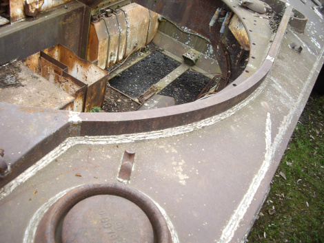
For the M32, they just bolted the new turret onto those. You can see the bolt heads in this photo of my model:
- Joined
- Sep 4, 2019
- Messages
- 9,491
- Points
- 113
- First Name
- Andrew
The turret was bolted down, it couldn’t rotate at all. The Sherman turret ring had a row of holes around it anyway, to which the turret race (the track with ball bearings) was bolted on gun tanks. They’re visible on this M4A2 hull:
(source)
For the M32, they just bolted the new turret onto those. You can see the bolt heads in this photo of my model:

Thanks for the confirmation.....thought that might be the case but good to have the confirmation.