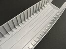
Landing Craft, Assault — Operation Infatuate I, 1 November 1944 (1:35 Gecko kit)

Jakko

Way past the mad part
SMF Supporter
Joined
Apr 28, 2018
Messages
11,036
Points
113
First Name
Jakko
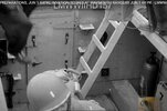
Here's a landing craft in Battleship Cove, Maryland, which is no help at all! :cool:
You’re right, but it’s a cool photo :smiling3: That’s an American LCV (Landing Craft, Vehicle), if I’m not mistaken — same sort of size as an LCA, but intended for delivering a one-ton truck or 36 troops ashore. The LCA also carried 36 troops, but couldn’t take vehicles because of its narrow bow ramp. The LCV was improved to become the LCVP, mainly by moving the steering position from on top of the rear deck (it’s the grey rectangular thing behind the stairs in the photo) to inside the hull alongside the engine, and adding two gunner’s positions behind the engine compartment.
 

Jakko

Way past the mad part
SMF Supporter
Joined
Apr 28, 2018
Messages
11,036
Points
113
First Name
Jakko
Would like to find more information on that door, quite an interesting thread.
The original small door or the later, larger one? :smiling3: Here is the outside of the large door, and this photo also shows that the bulkhead definitely either was made from steel riveted to a frame, or had steel plates riveted over the wood:

LCA steel bulkhead and door.jpeg
 

JR

Member of the Rabble and Pyromania Consultant
SMF Supporter
Joined
May 26, 2015
Messages
17,444
Points
113
Location
lincs
First Name
John
Thanks for that Jakko.

Although ply is stronger than solid timber against bending forces, solid timber is more durable in outdoor use. Plywood is used instead of solid wood for many purposes. But for some purposes, solid cannot be replaced with plywood. Both are better for their uses.

The wording of the description that you posted was very vague ( not you;) ) , some of us thought it was solid, other like me thought ply. Most interesting from an ex joiners point of view.
 

stillp

SMF Supporter
Joined
Nov 17, 2016
Messages
7,248
Points
113
Location
Rugby
First Name
Pete
Those planks must have been worth a fortune.
I’m pretty sure all the benches in my school chemistry labs were topped with mahogany, and they were built in the fifties. I know for certain that the original labs at Porton down (built at the same time, and with at least a couple of miles worth of bench when all added together) were topped with it. All the chairs and stools were made from beech though. The worst bit of this is that as the labs were gradually refurbished in the eighties and beyond the tops and furnishings were scrapped and replaced with more suitable materials. However because of the potential uses they had been subjected to over the years the wood could only be taken off site broken up as firewood. A great deal of it was simple burned on site as I recall.
The benches in 'my' college lab were topped with teak. Proper Burma teak, not the afrormosia that's passed off as teak in the garden furniture market. We had to rip out a row of benches to make room for some more machines, so I still have a decent chunk of it, about 4' x 2'6" x 2" under my wood lathe. I also have a table made from some of the Japanese oak.
Pete
 

stillp

SMF Supporter
Joined
Nov 17, 2016
Messages
7,248
Points
113
Location
Rugby
First Name
Pete
this photo also shows that the bulkhead definitely either was made from steel riveted to a frame, or had steel plates riveted over the wood:
I'd guess the latter. The door hinges seem to be riveted to reinforcement bar (angle iron?) which wouldn't be necessary if there was already a steel frame.
Pete
 

Tim Marlow

Little blokes aficionado
SMF Supporter
Joined
Apr 27, 2018
Messages
16,971
Points
113
Location
Somerset
First Name
Tim
Thanks for that Jakko.

Although ply is stronger than solid timber against bending forces, solid timber is more durable in outdoor use. Plywood is used instead of solid wood for many purposes. But for some purposes, solid cannot be replaced with plywood. Both are better for their uses.

The wording of the description that you posted was very vague ( not you;) ) , some of us thought it was solid, other like me thought ply. Most interesting from an ex joiners point of view.
Something I know very little about John, but could it still be ply in this instance, but faced on both sides with mahogany? Saying that, it doesn’t really make any difference to Jakko’s build does it ;)
 

Jakko

Way past the mad part
SMF Supporter
Joined
Apr 28, 2018
Messages
11,036
Points
113
First Name
Jakko
The wording of the description that you posted was very vague ( not you;) ) , some of us thought it was solid, other like me thought ply.
I also thought it would be plywood, but following Peter’s comments I suspect it was planks. That could make a difference to the model, because with planks you might “have” to scribe the seams between them. OTOH, I’ve not been able to spot any in photos, so …

I'd guess the latter. The door hinges seem to be riveted to reinforcement bar (angle iron?) which wouldn't be necessary if there was already a steel frame.
Quite possibly, yes. Not that it matters for modelling, but it’s nice to speculate :smiling3:

As for the model … I thought I’d be clever and size the drawings to 1:35 scale, then print them out, so I have an easy reference that I can just measure in directly. But look:
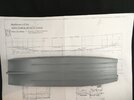
IMG_9967.jpeg

I made a mistake somewhere, so that the drawings are too large :sad: I guess I’ll have to give it a second try and return to the museum in Westkapelle to print them out again — the boat is big enough that you need an A3 sheet to fit it on, and I don’t have an A3 printer :smiling3: You could of course print out both halves on A4 and stick them together, but a single sheet is easier to work with.

That slight setback discovered, I took another good look at the floor parts, and decided that I will need to replace the whole troop compartment floor. It needs to run from frame 5 to 16, but the kit floor goes from about 6.5 to 16. What I did was trace the kit part onto a piece of 1 mm plastic card using the tip of a knife:
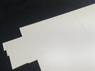
IMG_9961.jpeg

The pencil line is how long the floor needs to be. After cutting it out:
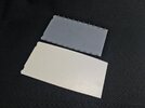
IMG_9962.jpeg

Trying it in the hull, you can see it’s now the right length:
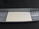
IMG_9963.jpeg

But it can’t fit between the frames, because it doesn’t have the cut-outs that the kit floor does. I first tried putting those in, but that’s fraught with problems. Then it hit me that I don’t need to add them at all, because I will be adding floatation cells between the frames — meaning I can just cut off the edges so the floor fits between the upright parts of the frames. I put the kit floor onto my replacement again, held it down tightly and used a sharp needle to prick at the end of the cut-outs in the kit part. Then I could just connect the marks with a knife and steel ruler:
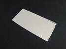
IMG_9964.jpeg

Marked at the bottom, cut at the top. That just left the front part, for which I just measured the distance between the ribs. With the sides cut off, the floor fits inside the hull:
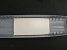
IMG_9965.jpeg

And the difference with the kit part:
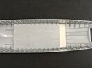
IMG_9966.jpeg

Then the planking. It turns out the kit’s planks are 4 mm wide, and I saw no good reason to deviate from that, so I just marked out the centreline and then a line every 4 mm:
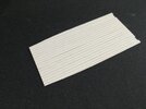
IMG_9968.jpeg

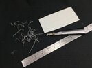
All that was left to do was go over the lines with a Tamiya plastic cutter/scriber/whatever:
IMG_9969.jpeg

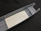
I decided I could also salvage the forward part of the kit’s front floor:
IMG_9970.jpeg

I simply cut it off at the third frame, and will now have to build the sloping floor and the floors for the steering and MG positions as well.
 

JR

Member of the Rabble and Pyromania Consultant
SMF Supporter
Joined
May 26, 2015
Messages
17,444
Points
113
Location
lincs
First Name
John
Great idea there , looks good as well . Should think your relieved not having to scribe around those uprights .
 

Tim Marlow

Little blokes aficionado
SMF Supporter
Joined
Apr 27, 2018
Messages
16,971
Points
113
Location
Somerset
First Name
Tim
Nice scratchy work Jakko. Not seen a scrawker used in ages ;) Are you, or do you need to, replicate the small square cut outs shown on the original kit part?
 

Jakko

Way past the mad part
SMF Supporter
Joined
Apr 28, 2018
Messages
11,036
Points
113
First Name
Jakko
Should think your relieved not having to scribe around those uprights .
Very much so, yes. It would be a minor nightmare getting them all to line up correctly, on both sides, not to mention I couldn’t find a good way to cut them wide enough to clear the ribs in one go — I tried making one using a hacksaw (being thicker than a modelling saw) but even that wasn’t enough.

Not seen a scrawker used in ages ;)
I take it you mean the Tamiya (Olfa, really) plastic scriber? I use that quite a lot for things like this, and I have a smaller one by Trumpeter too for when I need to make narrower or lighter cuts.

Are you, or do you need to, replicate the small square cut outs shown on the original kit part?
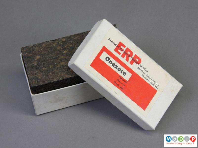
Happily, no. Those are for the legs of the bench seats, and because Gecko got the floor length wrong, the seats are obviously too short as well to fit the new floor, so I will have to scratchbuild the seats. This is not as big a deal as it sounds like, because Gecko got the benches along the sides wrong anyway :smiling3: It seems that most LCAs did not have slatted wing benches (as the drawings call them) but solid ones, filled with something called “onazote”, which seems to be a foam made from (natural?) rubber:

p77_4.jpg


… or with cork, either of course for additional buoyancy. So these benches have enclosed sides and a simple, flat top, as you can see in this photo I posted earlier:

lca-steel-bulkhead-and-door-jpeg.487258


Or, of course, in this cross-section from drawing 1:

LCA cross-section fore-aft.png
 

Tim Marlow

Little blokes aficionado
SMF Supporter
Joined
Apr 27, 2018
Messages
16,971
Points
113
Location
Somerset
First Name
Tim
I take it you mean the Tamiya (Olfa, really) plastic scriber? I use that quite a lot for things like this, and I have a smaller one by Trumpeter too for when I need to make narrower or lighter cuts.
Yep, that’s the one. Scrawker is the proper name for it. They don’t scribe, because as you know, they actually remove material. Made my own about thirty years ago before they were commercially available. They were a common tool in finescale railway modelling for years. Not that hard to make using an old modelling knife blade and a motor tool and grind stone.
I use a Tamiya one these days, and have a heavy duty one from a DIY shop (sold as an acrylic cutter) for use when cutting heavy sheet. Lino cut art tools can be useful as well, especially if you want a V shaped, rather than square shaped, trench. Very useful for marking T and G planking on small scale models. They usually fit in a pen handle, by the way.
 

Jakko

Way past the mad part
SMF Supporter
Joined
Apr 28, 2018
Messages
11,036
Points
113
First Name
Jakko
Never heard of that name before :smiling3: I tend to call it a plastic cutter, because it works very well if you need to make long cuts through thick plastic card. You do need to make sure you take into account the width of the material it removes, though.
 

Tim Marlow

Little blokes aficionado
SMF Supporter
Joined
Apr 27, 2018
Messages
16,971
Points
113
Location
Somerset
First Name
Tim
Never heard of that name before :smiling3: I tend to call it a plastic cutter, because it works very well if you need to make long cuts through thick plastic card. You do need to make sure you take into account the width of the material it removes, though.
Best part is that it doesn’t leave a ridge either side of the cut. That’s what makes it great for planking etc.
 

Jakko

Way past the mad part
SMF Supporter
Joined
Apr 28, 2018
Messages
11,036
Points
113
First Name
Jakko
Exactly the reason I like using it for those things, yes :smiling3: I had cut the floor with a knife, and needed to file down all of the edges to get them to be flat with the rest of the plate again.
 

Jakko

Way past the mad part
SMF Supporter
Joined
Apr 28, 2018
Messages
11,036
Points
113
First Name
Jakko
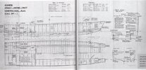
Another drawing has surfaced!

LCA plan 2:1215:39.jpg

This with thanks to someone on Missing-Lynx. It’s actually a scan from a book about the LCA, Assault Landing Craft: Design, Construction and Operations by Brian Lavery, but that goes for silly money, so I asked the person who mentioned it, to scan it for me (The above is a reduced-size version, because the forum would not like the full-size one. You can download it here if you want — note that it’s 7.7 MB, though.

Anyway, this looks like a very early plan — my idea is that the 39 in the drawing’s number, 2/1215/39, is the year it was made. The drawing has various details different than in the late-1942 plans we already had. Importantly, it doesn’t have the machine-gun position on the port side, which clearly makes this a very early boat. It also doesn’t show the round engine deck hatch which is known to be a later modification, has three slatted benches rather than only the centre one like that, and the floor in the bow passage is the type with the kink in it, that I took to be a later modification. What I now think happened, is that this floor caused too much water to flow straight into the troop compartment, so they lowered the floor and added an armour plate below the doors to keep most of that water out. That plate, BTW, turns out to be hinged so it can fold down and doesn’t form a trip hazard like I thought it would be — or so I only noticed when I looked more closely at it in the bow detail drawings.
 

Jakko

Way past the mad part
SMF Supporter
Joined
Apr 28, 2018
Messages
11,036
Points
113
First Name
Jakko
I said I saw no good reason to deviate from the plank width in the Gecko floor, but now I do :smiling3: On the drawings, the planks are 9 inches wide, or 6.5 mm in 1:35 — much more than the kit’s 4 mm. I had also overlooked the baling hatches, so I scribed new planks on the other side of the replacement floor plate:

IMG_9977.jpeg

And because the forward half of the main floor in an LCA is not flat, but Gecko’s part is, I also had to correct the height of frames 6 through 11 underneath it:

IMG_9978.jpeg

These are just bits of plastic card, 5.5 mm high like the ribs I didn’t correct. I still need to bend the floor to fit, but not yet because I don’t want to find out later I need to scribe or cut more bits to go on it.
 

Jakko

Way past the mad part
SMF Supporter
Joined
Apr 28, 2018
Messages
11,036
Points
113
First Name
Jakko
I will end up scratchbuilding most of the interior, by the looks of it … However, the hull shape seems to be spot on, if I put it on the drawings that I printed out at 1:35 scale, and that is the hardest bit, at least for an armour modeller like me :smiling3: I’m sure that if I built model ships from balsa then I wouldn’t even bother with a kit — but then, I would probably also not be as concerned with getting everything right as I am now ;)
 
Top