You are using an out of date browser. It may not display this or other websites correctly.
You should upgrade or use an alternative browser.
You should upgrade or use an alternative browser.
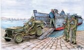
Landing Craft, Assault — Operation Infatuate I, 1 November 1944 (1:35 Gecko kit)
- Thread starter Jakko
- Start date
Excellent silkpursery.
Neat backstory and top notch for your corrections Jakko 

Well, what a fascinating read that was!! Loving how this looks Jakko.... I have a part built Italeri LC on the shelf, and, compared to what I've just watched you produce,I might as well have just bought a shoe box and called it an LC!!
Outstanding stuff mate, looking forward to the next update
Outstanding stuff mate, looking forward to the next update

- Joined
- Apr 28, 2018
- Messages
- 10,951
- Points
- 113
- First Name
- Jakko
Thanks 


The worst thing is that all this is even necessary … Gecko seems to have taken quite a lot of shortcuts with this modeltop notch for your corrections Jakko

The LCVP, you mean, or the LCM (3)? The LCVP is the American equivalent to the British LCA, of similar size, but the LCM (3) is much larger, able to take a medium tank. If you have the Italeri kit of that, it’s far better than the Trumpeter kit of the same vessel, BTW.I have a part built Italeri LC on the shelf, and, compared to what I've just watched you produce,I might as well have just bought a shoe box and called it an LC!!
I'll get it off the shelf and take a closer look....as far as I remember though,it seemed quite "lacking" at the time.... I'll double check 

Scratchbuilder
SMF Supporter
LOLAlmost, yeah … But at least I can use most of the detail parts that are hard to scratchbuildThough I can still go, “Here is the box it came in, and it’s filled to capacity with the parts I had left over.”
Thanks

- Joined
- Apr 28, 2018
- Messages
- 10,951
- Points
- 113
- First Name
- Jakko
I think I’ll post a photo of what I have left after the model is finished …
For now, though, it’s more plastic card. I made templates for pieces to go the inside hull sides by drawing a line along the bottom of the hull (since the floor inside pretty much follows the curve of that) and marking the front and rear lines. I then cut that out, deliberately too tall, and fit it inside. It mostly fit, except for being slightly too short at the front, and then I just drew a line alone the top edge of the hull to get the shape there too.
Once that template was done, I could put it onto my scanner so I got it on the computer. That let me draw around it in Adobe Illustrator, correct the size at the front, then print that drawing out twice onto a sheet of paper.
Next, I glued the templates to a sheet of 1 mm plastic card with PVA glue:
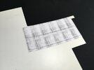
(My printer’s toner cartridge smudges a lot, yes ) Then it was a matter of cutting out along the lines, trial-fitting and filing to size:
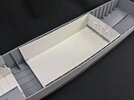
All this is because the later boats had the space between the frames filled with blocks to give additional buoyancy in case the boat had a leak, meaning the frames themselves all but disappeared. If you don’t want to add these, then the frames are not deep enough and need about 1 mm added to them.
Next step was to mark out the positions of the frames, by putting the walls inside the hull and marking their tops and bottoms with a pencil, then connecting them with a ruler. After that, I just scribed a line on both sides of each pencil line:
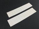
With these plates, the roof won’t fit anymore, because it has angle-iron ribs along its underside. That’s not a problem:
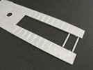
… because those have to go anyway I chiselled them off because though the real boat did have angle iron ribs, they were much deeper than the kit shows them, and they were behind the frames rather than lining up with them as per the kit part.
For now, though, it’s more plastic card. I made templates for pieces to go the inside hull sides by drawing a line along the bottom of the hull (since the floor inside pretty much follows the curve of that) and marking the front and rear lines. I then cut that out, deliberately too tall, and fit it inside. It mostly fit, except for being slightly too short at the front, and then I just drew a line alone the top edge of the hull to get the shape there too.
Once that template was done, I could put it onto my scanner so I got it on the computer. That let me draw around it in Adobe Illustrator, correct the size at the front, then print that drawing out twice onto a sheet of paper.
Next, I glued the templates to a sheet of 1 mm plastic card with PVA glue:

(My printer’s toner cartridge smudges a lot, yes
 ) Then it was a matter of cutting out along the lines, trial-fitting and filing to size:
All this is because the later boats had the space between the frames filled with blocks to give additional buoyancy in case the boat had a leak, meaning the frames themselves all but disappeared. If you don’t want to add these, then the frames are not deep enough and need about 1 mm added to them.
Next step was to mark out the positions of the frames, by putting the walls inside the hull and marking their tops and bottoms with a pencil, then connecting them with a ruler. After that, I just scribed a line on both sides of each pencil line:

With these plates, the roof won’t fit anymore, because it has angle-iron ribs along its underside. That’s not a problem:

… because those have to go anyway
 I chiselled them off because though the real boat did have angle iron ribs, they were much deeper than the kit shows them, and they were behind the frames rather than lining up with them as per the kit part.
Last edited:
".....and so it goes....."
Scratchbuilder
SMF Supporter
Jakko,
Still going strong on this build. Really enjoying your modelling.
Still going strong on this build. Really enjoying your modelling.
- Joined
- Apr 28, 2018
- Messages
- 10,951
- Points
- 113
- First Name
- Jakko
Thanks for the praise, but I’m just muddling through  A tricky bit I’m up against now is how to drill a series of holes through those side plates, all at the same angle (that’s not 90 degrees, but more like 45).
 A tricky bit I’m up against now is how to drill a series of holes through those side plates, all at the same angle (that’s not 90 degrees, but more like 45).
Waspie
SMF Supporter
Wow, that's quite some impressive work Jakko. You really go that extra mile for accuracy. 

- Joined
- Apr 28, 2018
- Messages
- 10,951
- Points
- 113
- First Name
- Jakko
Here’s more proof that this kit is definitely not shake-and-bake, then  Well, that’s to say, it most definitely can be if you want it to be, but not, as I’ve mentioned before, if you want it accurate …
I’ve already shown the basic side plates, to represent the buoyancy blocks between the frames, but it also needs angled rods to support the deck. On the real boat, these were pieces of tube with the ends flattened, and then bolted to the frames and to a piece of angle iron underneath the deck (like the ones I cut off earlier ) but you only need to care about the flattened ends if you don’t add the buoyancy aids. If you do, then all you need to do is drill 22 holes at a 45-degree angle for the bits of rod to go into … easy
I had to give that some thought before I figured out a good way to make a simple jig:
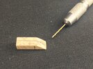
This is just a bit of wood from the tail of a fireworks rocket that I picked up from the street on New Year’s Day. No particular reason to use that, except that it’s fairly hard and not something soft like balsa that modellers often have handy. I sawed it off at a 45-degree angle, then drilled a hole through it at right angles to the cut face, the hole being one size (0.05 mm) larger than the drill I was going to use. The way to use it is to first stick the drill through it and lightly poke the drill into the plastic where the hole is to go:
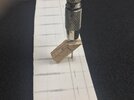
This is made easier by first using a sharp needle or something to mark the right spot. Then pivot down to 45 degrees, making sure to line up the jig with the frame line — that’s what the pencilled lines on the jig are for:
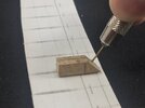
Then firmly hold the jig in place and drill through the plate; repeat for the remaining frames:
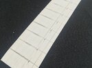
The holes are about 25 mm from the lower edge of the plate. Better to measure from below, because the lower edge is the one that you can more easily work from: the top one will be out of sight and so doesn’t need to be overly accurate.
From photos, it seems the positions of the support rods varied: on some boats they were behind the frames (as in: right behind them, because of being bolted to them) but at least some boats had them alternating. That is, on the rear of one frame, then on the front of the frame behind, then on the rear of the next, etc. I went for all of them behind the frames.
And glued into the boat:
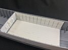
For this, I put tube cement onto each of the frames and then stuck the side plate in. It’s easier if you carefully bend it to fit a bit first, before reaching for the glue, but this one happened to be tight between frame 5 and the engine bulkhead. I added the other side after taking this photo, but that needed clamping, as I had made it slightly shorter so I can fit the armour plate for the steering shelter between it and the frame later on.
For those wondering if all this is really necessary, because how much can you really see of all that stuff anyway? Well, this much:
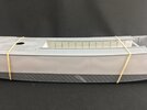
A little experimentation showed that you can see everything that’s more than about 3 mm below the deck. The tops of the holes I drilled are about 7 mm below it, so they’re clearly visible if you look at a low angle.
You can also see I drew two horizontal lines. These mark the top edges of the planks I’ll fit later, which held the buoyancy blocks in place on the real thing. I couldn’t fit them yet, because of the way the plates need to curve to follow the hull. Glue the planks on before installing the plates and you’re making life more difficult for yourself.
Photos from two different wrecks in the 1980s show one with two planks and one with four, so there’s scope for variation. Measuring in the photos, I worked out that the two planks are about 7.5 mm and 19.5 mm from the floor, while the four planks were at 10 mm, 17 mm, 23.5 mm, and 31.5 mm — all these are the top edges, BTW. That top plank will be out of sight just about entirely, though. The planks were straight and didn’t follow the curve of the floor or deck, as far as I can tell, so I marked out the distances on the first and last frames, then just drew horizontal lines through them.
 Well, that’s to say, it most definitely can be if you want it to be, but not, as I’ve mentioned before, if you want it accurate …
I’ve already shown the basic side plates, to represent the buoyancy blocks between the frames, but it also needs angled rods to support the deck. On the real boat, these were pieces of tube with the ends flattened, and then bolted to the frames and to a piece of angle iron underneath the deck (like the ones I cut off earlier

I had to give that some thought before I figured out a good way to make a simple jig:

This is just a bit of wood from the tail of a fireworks rocket that I picked up from the street on New Year’s Day. No particular reason to use that, except that it’s fairly hard and not something soft like balsa that modellers often have handy. I sawed it off at a 45-degree angle, then drilled a hole through it at right angles to the cut face, the hole being one size (0.05 mm) larger than the drill I was going to use. The way to use it is to first stick the drill through it and lightly poke the drill into the plastic where the hole is to go:

This is made easier by first using a sharp needle or something to mark the right spot. Then pivot down to 45 degrees, making sure to line up the jig with the frame line — that’s what the pencilled lines on the jig are for:

Then firmly hold the jig in place and drill through the plate; repeat for the remaining frames:

The holes are about 25 mm from the lower edge of the plate. Better to measure from below, because the lower edge is the one that you can more easily work from: the top one will be out of sight and so doesn’t need to be overly accurate.
From photos, it seems the positions of the support rods varied: on some boats they were behind the frames (as in: right behind them, because of being bolted to them) but at least some boats had them alternating. That is, on the rear of one frame, then on the front of the frame behind, then on the rear of the next, etc. I went for all of them behind the frames.
And glued into the boat:

For this, I put tube cement onto each of the frames and then stuck the side plate in. It’s easier if you carefully bend it to fit a bit first, before reaching for the glue, but this one happened to be tight between frame 5 and the engine bulkhead. I added the other side after taking this photo, but that needed clamping, as I had made it slightly shorter so I can fit the armour plate for the steering shelter between it and the frame later on.
For those wondering if all this is really necessary, because how much can you really see of all that stuff anyway? Well, this much:

A little experimentation showed that you can see everything that’s more than about 3 mm below the deck. The tops of the holes I drilled are about 7 mm below it, so they’re clearly visible if you look at a low angle.
You can also see I drew two horizontal lines. These mark the top edges of the planks I’ll fit later, which held the buoyancy blocks in place on the real thing. I couldn’t fit them yet, because of the way the plates need to curve to follow the hull. Glue the planks on before installing the plates and you’re making life more difficult for yourself.
Photos from two different wrecks in the 1980s show one with two planks and one with four, so there’s scope for variation. Measuring in the photos, I worked out that the two planks are about 7.5 mm and 19.5 mm from the floor, while the four planks were at 10 mm, 17 mm, 23.5 mm, and 31.5 mm — all these are the top edges, BTW. That top plank will be out of sight just about entirely, though. The planks were straight and didn’t follow the curve of the floor or deck, as far as I can tell, so I marked out the distances on the first and last frames, then just drew horizontal lines through them.
Last edited:

