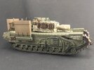
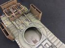
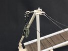
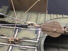
Churchill Mk. IV AVRE with Small Box Girder Assault Bridge Mk. II

Jack L

SMF Supporter
Joined
Jul 25, 2018
Messages
1,007
Points
113
First Name
Jack
I think I would be nervous too — the manual doesn’t say to actually test the waterproofing, it just assumes the crew does the work correctly …


Then I have some more for you, about that waterproofing :smiling3: Of the 14 tanks landed at Westkapelle on 1 November 1944, only four or perhaps five didn’t drown … However, none drowned in coming ashore — the rest got stuck on the remains of the dyke and, despite frantic efforts to tow them out with other tanks and armoured bulldozers, drowned when the tide rose too high.

For example, from the war diary of 87 Assault Squadron, Royal Engineers:

It says LCT 757, but that should be 737, which carried assault group Bramble (though the Royal Engineers consistently talk about “lanes” where 1 Lothians and Border Yeomanry, who supplied the Crabs and Sherman command tanks, refer to “assault groups”).

The same war diary also has this report from assault group Apple, carried in LCT 1005:

The bridge AVRE referred to above is not T68927, number A2A, that I’m building, but A2B (the “me” is Lt. J C Ramsay of the Royal Engineers). Just the other day, I came across this picture, that I had never seen before, in a Canadian movie news report about the landings:

View attachment 485867

Visible there is LCT 1005, the SBG bridge lying from its bow ramp is clearly visible, as are the two Crabs bogged down this side of it and one behind; AVRE A2B was either to the right of the picture or still inside the LCT, and in either case, A2C (“fascine AVRE” in the report) is also inside the LCT at this point, because it got stuck on the bridge after landing.

Notice the report mentions A2A as being used to try and tow others free. It ended its war a bit higher up on the “beach” but never did make it into the village, but it’s not clear to me why. It doesn’t look like it got stuck, but maybe it did, just not as badly as the others?


Thanks. Pretty much all of it is straight from the box — the only parts I replaced for being overscale, were the tie rods and hooks for the wading ducts. AFV Club kits all have very fine details, though that also makes them harder to build than many other brands.
From what I have read, and without looking back through, I think one of the pictures you have posted confirms this, only the driver would be in the tank when coming off the landing craft into the water, the rest would sit on top just in case, then get in once on solid ground.
 

Tim Marlow

Little blokes aficionado
SMF Supporter
Joined
Apr 27, 2018
Messages
16,782
Points
113
Location
Somerset
First Name
Tim
From what I have read, and without looking back through, I think one of the pictures you have posted confirms this, only the driver would be in the tank when coming off the landing craft into the water, the rest would sit on top just in case, then get in once on solid ground.
I’ve read that as well, though the commander would still be hooked up to the intercom set…..apparently there was a switch on the dash that would blow the waterproofing off when they reached land.
There’s a good description of it in here…
070E1FCD-FE1F-47DE-A035-954036134778.jpeg
 

Jakko

Way past the mad part
SMF Supporter
Joined
Apr 28, 2018
Messages
10,821
Points
113
First Name
Jakko
From what I have read, and without looking back through, I think one of the pictures you have posted confirms this, only the driver would be in the tank when coming off the landing craft into the water, the rest would sit on top just in case, then get in once on solid ground.
I don’t think this was the official intent, though. The deep-wading manual gives the impression the whole crew is meant to be on board, but I think it’s a safe bet that the crews would judge the relative dangers for themselves when deciding whether or not to :smiling3:

I’ve read that as well, though the commander would still be hooked up to the intercom set…..apparently there was a switch on the dash that would blow the waterproofing off when they reached land.
Luckily, I have the official manual for this particular tank :smiling3: (Well, not the AVRE but the regular Churchill, but that can’t have been very different.)
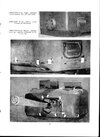
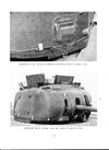
There was Cordtex (in modern terms: detonating cord) behind all of the waterproofing fabric except that around the gun muzzle of the regular tank (I suppose there was on the AVRE). Here is how it fit to the turret, for example:

Churchill 6ft Wading Instructions p. 35.jpgChurchill 6ft Wading Instructions p. 36.jpg

The Cordtex on the turret was to be plugged into the socket for the inspection lamp in the turret, that for the bow machine gun and front hull roof ventilator into the driver’s instrument panel, and the Cordtex on the insides of the hull rear sealing plates also into the inspection lamp socket. The sockets were to be taped over to prevent accidentally inserting the plugs or wires.

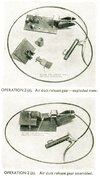
The in- and outlet ducts were held on by the tie rods, which attached to the release gear in the centre of the engine deck. That looks like this:

Churchill 6ft Wading Instructions p. 15.jpeg

It’s really a pretty simple affair: rings or hooks (not sure which) at the ends of the tie rods go around the little vertical posts, with the square plate holding them down. The smaller plate holds the square plate in position, and is itself retained by a plunger while the spring tries to push both plates off. A bicycle handbrake lever attached to a Bowden cable retracts the plunger, the two plates fly off and the ducts’ own weight pulls them off the tank.

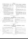
Here is the procedure that was to be followed right after landing:

Churchill 6ft Wading Instructions p. 51.jpg

This also tells you why there was no Cordtex on the gun: just fire an AP round :smiling3: This was not possible with an AVRE, of course, as it had nothing but HE in the first place. But a bit of Cordtex around the outside of the mortar muzzle would work fine, I imagine.
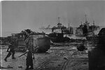
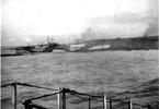
And here is an AVRE at Westkapelle, with only one of its ducts remaining on the tank, and the rear one visible on the ground behind it:

Red Beach 2.jpeg

I’m not 100% sure which AVRE this is, but doing some impromptu deduction just now, it’s not an SBG or fascine carrier (because there’s no hardware for those on it), meaning it’s either T69114/B, No. A3 Minotaur, or T172224, No. A2 (name unknown). That means it’s almost certainly the latter, because A3 had full-length track guards while this tank is missing the centre section.
 
Last edited:

JR

Member of the Rabble and Pyromania Consultant
SMF Supporter
Joined
May 26, 2015
Messages
17,275
Points
113
Location
lincs
First Name
John
Thanks for the additional history.
Reading of how they attempted to come ashore , the getting bogged down, and Spr Rampley wading ashore like that while under mortar fire . All that to contend with and then following the instructions for removing the water proofing ! Should think they had nightmares for ever after that .
 

Jakko

Way past the mad part
SMF Supporter
Joined
Apr 28, 2018
Messages
10,821
Points
113
First Name
Jakko
I suspect they had severely underestimated how bad the landing “beach” was going to be. It’s a sandy beach today, but in 1944 it was actually the ruins of the dyke that had kept the sea at bay for over 500 years, and that been gradually built up over all that time. Most of the “beach” was not sand but mud from the clay core of the dyke (the soil on Walcheren being mostly heavy, grey clay) that had by 1 November 1944 been saturated by the sea for four weeks. Add to this large blocks of basalt that littered the clay, from the revetment on the outside of the dyke, and you have very difficult going for any vehicle, even tracked ones.

Plus, of course, the intent was never to land the tanks here anyway — they were supposed to land a hundred metres or so further north, where the dyke was intact. That is to say, in the same area where these three LCI(S)’s [Landing Craft, Infantry (Small)] were photographed:

LCI(S) at Westkapelle.jpg

These were the very first ashore, the troops on the dyke are men from No. 41 (RM) Commando. As you can see, the dyke is not overly damaged here, so this would have let the tanks simply drive up it with no chance at all of bogging down: the worst driving hazard would have been slipping down the basalt slope. However, the intensity of the German fire caused the LCTs carrying the tanks to go further south, into the gap that had been bombed into the dyke, because they were sheltered from the gunfire there (but not the mortars, of course).

I just remembered I have a photo of what the dyke looked like before the RAF blasted it to bits on 3 October 1944:

Westkapelle dyke mid-WWII.jpg

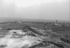
This photo looks to the west-northwest, approximately, from a high dune southeast of the village where the Germans had built a radar station; notice the trenches, AA gun etc. in the foreground. The initial gap that was bombed in the dyke ran from the windmill (which was destroyed in the bombing) to about where the light on the dyke is (the post with supports, between the mill and the fishing boats). The intended tank landing beach was to the right of the windmill as seen here, but in fact they landed to its left.

The gap was widened later by a second bombing raid and the scouring of the tides going in and out twice a day. None of the buildings you can see on the right were more than ruins after the first attack. My great-uncle and -aunt and their toddler son lived in one of them, which is probably just in the photo (but it’s hard to say); after the bombing, their house had gone, nothing but a huge, water-filled bomb crater in its place. They themselves were nowhere to be found until his brother (my grandfather) decided to dredge the crater and found all three without so much as a scratch on them, except my great-aunt had a broken leg.
 

Richard48

SMF Supporter
Joined
Apr 27, 2018
Messages
1,406
Points
113
Location
Clacton on sea
First Name
Richard
Really interesting read Jakko.Got me back into Churchill building mode.Ive just ordered x2 Churchill 1/2 concersions for the Afv club kits from International models asia.
Richard
 

Jakko

Way past the mad part
SMF Supporter
Joined
Apr 28, 2018
Messages
10,821
Points
113
First Name
Jakko
You’ll be building them sometime next year, then ;) Well, it’s not that bad, but count on several (two to four or so) months before you get them in the mail, very neatly and tightly wrapped in packing paper.
 

Richard48

SMF Supporter
Joined
Apr 27, 2018
Messages
1,406
Points
113
Location
Clacton on sea
First Name
Richard
You’ll be building them sometime next year, then ;) Well, it’s not that bad, but count on several (two to four or so) months before you get them in the mail, very neatly and tightly wrapped in packing paper.
I ordered before from them and were ok to deal with.Hoping they dont take too long to arrive.But ive got to get kits etc before i start.Might start easy by doing an Iraqi Mark v11 of the 1950s.I saw a Jordanian one on the i modeller site but im not sure if Jordan used them.Maybe the modeller got it mixed up with an Iraqi one.
Richard
 

Jakko

Way past the mad part
SMF Supporter
Joined
Apr 28, 2018
Messages
10,821
Points
113
First Name
Jakko
Yes, makes it all come much more alive than the short version :smiling3:
 

Jakko

Way past the mad part
SMF Supporter
Joined
Apr 28, 2018
Messages
10,821
Points
113
First Name
Jakko
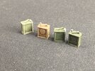
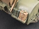
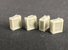
I’ve not done much work on this model over the past week and a half or so, but we’re slowly getting there … I replaced the kit’s 2-gallon POW (Petrol, Oil, Water) cans by ones from Resicast:

IMG_9909.jpeg

When I wanted to buy them at a convention a few months ago, though, I was told “I can’t sell those to you, we forgot to put in the handles.” When I replied that those aren’t the hardest thing to make, so I would like this set despite the packing error, I got a discount :smiling3:

Anyway, the plastic ones in the kit are not very good, as they lack the reinforced edges, and the Resicast set includes cans with specific brand names and logos on them, so I used some of those for variation. Other good replacements are in Bronco’s Field Accessoires Set.

After a couple of coats of paint:

IMG_9921.jpeg

I first put on an undercoat of Mr. Surfacer 1000, followed by green or brown for the base colour, then thinned Army Painter Strong Tone, and a drybrush of a random colour that was lighter than the base. The caps were then painted with grey because early in the war, these were brass, but apparently, that was soon replaced by some cheap metal.

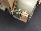
Two of them on the tank:

IMG_9922.jpeg

I glued all four to the racks and added the kit’s retaining straps over them. There is a second part representing a rod with a butterfly nut to go behind the cans, but I’ve left that off for now because I wanted to wait until the glue dried on the other pieces, so as not to inadvertently move them. Before I do that, I think I will also add the text WATER on one of the cans that have no logo.
 
Last edited:

JR

Member of the Rabble and Pyromania Consultant
SMF Supporter
Joined
May 26, 2015
Messages
17,275
Points
113
Location
lincs
First Name
John
I suspect they had severely underestimated how bad the landing “beach” was going to be. It’s a sandy beach today, but in 1944 it was actually the ruins of the dyke that had kept the sea at bay for over 500 years, and that been gradually built up over all that time. Most of the “beach” was not sand but mud from the clay core of the dyke (the soil on Walcheren being mostly heavy, grey clay) that had by 1 November 1944 been saturated by the sea for four weeks. Add to this large blocks of basalt that littered the clay, from the revetment on the outside of the dyke, and you have very difficult going for any vehicle, even tracked ones.

Plus, of course, the intent was never to land the tanks here anyway — they were supposed to land a hundred metres or so further north, where the dyke was intact. That is to say, in the same area where these three LCI(S)’s [Landing Craft, Infantry (Small)] were photographed:

View attachment 485978

These were the very first ashore, the troops on the dyke are men from No. 41 (RM) Commando. As you can see, the dyke is not overly damaged here, so this would have let the tanks simply drive up it with no chance at all of bogging down: the worst driving hazard would have been slipping down the basalt slope. However, the intensity of the German fire caused the LCTs carrying the tanks to go further south, into the gap that had been bombed into the dyke, because they were sheltered from the gunfire there (but not the mortars, of course).

I just remembered I have a photo of what the dyke looked like before the RAF blasted it to bits on 3 October 1944:

View attachment 485975

This photo looks to the west-northwest, approximately, from a high dune southeast of the village where the Germans had built a radar station; notice the trenches, AA gun etc. in the foreground. The initial gap that was bombed in the dyke ran from the windmill (which was destroyed in the bombing) to about where the light on the dyke is (the post with supports, between the mill and the fishing boats). The intended tank landing beach was to the right of the windmill as seen here, but in fact they landed to its left.

The gap was widened later by a second bombing raid and the scouring of the tides going in and out twice a day. None of the buildings you can see on the right were more than ruins after the first attack. My great-uncle and -aunt and their toddler son lived in one of them, which is probably just in the photo (but it’s hard to say); after the bombing, their house had gone, nothing but a huge, water-filled bomb crater in its place. They themselves were nowhere to be found until his brother (my grandfather) decided to dredge the crater and found all three without so much as a scratch on them, except my great-aunt had a broken leg.
Thanks for that Jakko, great photos as well .:thumb2:
 

Jakko

Way past the mad part
SMF Supporter
Joined
Apr 28, 2018
Messages
10,821
Points
113
First Name
Jakko
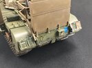
The brackets for the POW cans are now on completely, and painted:

IMG_9934.jpeg

My advice, though, would be to fit the cans and their brackets before painting the model, as following my example makes it very hard to paint the brackets.

But that done, I could go on to the markings. Here is the right-hand side:

IMG_9935.jpeg

(The turret is not on straight because the winch cable is stuffed inside the hull, to keep it out of the way.)

The registration number T68927/B is correct for this tank, though the /B is speculative. However, another AVRE at Westkapelle, T69114, had the same addition so I think it’s at least plausible. The numbers were assembled by cutting digits from registration numbers on the decals sheet for Tamiya’s Cromwell kit, while the /B is from this AVRE’s decal sheet.

The hand-painted BRAMBLE LCT5 is also speculative, but again, T69114 had a similar marking there, CHERRY LCT6, in the same style. The words Bramble and Cherry were the names of the assault groups (or in Royal Engineers terms: lanes) to which the tanks were assigned, and the 5 and 6 the numbers of the landing craft in which they were to embark. That’s not the number on the bow, by the way, but a separate “Loading Table Index Number” (LTIN) used within Operation Infatuate: LTIN 5 was LCT 737, LTIN 6 was LCT 650.

The rear markings are fairly simple:

IMG_9936.jpeg

Except for the WATER decal, which is from the Bronco accessories set, all of these are from the kit’s decals. Arm of Service marking 1234 on a blue square is 6 Assault Regiment, Royal Engineers, the bull’s head on a yellow triangle is 79 Armoured Division.

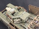
And the turret:

IMG_9937.jpeg

The star on the roof is from a Star Decals set, the A2A on the rear of the bin is hand-painted because I couldn’t find suitable decals among my many spares. It’s also speculative, but once more, T69114 had its number (A3) in a similar location and style. However, as the bin of A2A is missing in all photos I know of the wreck, it’s impossible to be sure of how it looked on this tank.
 
Last edited:

Jakko

Way past the mad part
SMF Supporter
Joined
Apr 28, 2018
Messages
10,821
Points
113
First Name
Jakko
Almost there …
 

Jakko

Way past the mad part
SMF Supporter
Joined
Apr 28, 2018
Messages
10,821
Points
113
First Name
Jakko
Unique in that I’m probably the only one crazy enough to try and replicate this exact tank, sure :smiling3:

Small steps to get to the finish line … I started by adding the Bowden cable that connects to the release mechanism for the wading ducts:

IMG_9938.jpeg

This is some 0.25 mm nylon fishing line that I painted black, then glued into a hole I drilled through the mechanism in the approximate place where the cable attached on the real thing. It’s far too long, but that’s not a problem because it will go up onto the turret roof and into the commander’s hatch, where it will disappear out of sight. Making it much too long means it will be easy to keep it in there :smiling3:

On the bridge, I added the quick-release mechanism and one of the two blocks supplied in the kit:

IMG_9939.jpeg

As you can see, they attach with clasps and pins, again just the ones that come in the kit. The cable is 0.25 mm fishing line again, glued into a hole I drilled into the side of the release mechanism.

I then attached the other block on the tank side to the cable on the front of the winch cage in a similar way:

IMG_9942.jpeg

That done, I threaded the winch cable through the blocks and used it to pull up the bridge — until the little cable on the winch cage, broke free from the clasp, because it pulled through the joint between the clasp and the pin :sad: The problem is that AFV Club moulded a hole in only one side of the clasps, then supply pins that are exactly long enough to fit. Had they put the hole all the way through both sides and supplied longer pins, there would be zero risk of this happening. My solution was to run a 1 mm drill through the hole and use it to open up the other side as well, then put in a length of 1 mm brass rod, as you can see in the photo. Once I had attached the block to the cable with that, I superglued it in place. I will have to see about glueing the ring from the AFV Club pin to it; I tried, but it didn’t want to cooperate yet, so I may end up leaving it off entirely.

With that fix made, I threaded the winch cable through the blocks again and used it to pull up the bridge to travelling position — this works very well, even better than I had expected. I could then determine how long I needed to cut the cable for installing an eye on the end, before carefully lowering the bridge again (by holding the bridge, not the cable!) so I could glue the eye on. That is still drying, because it needs to be firmly attached before I will hook everything up.
 
Top