A Different Direction..............

Dave Ward

Still Trying New Things
SMF Supporter
Joined
Apr 27, 2018
Messages
8,686
Points
113
Location
South Gloucestershire
First Name
David
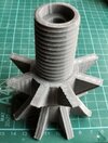
Spool nut printed - it stuck well - I think I've got the bed temperature a little high - the bottom surface has the texture of the new build plate....................
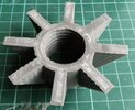
DSCF4080.JPG
The big question - will the nut fit the thread??
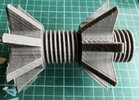
DSCF4079.JPG
The answer is YES!!! a bit rough at first, but once I'd run it up and down the thread, and taken off the sharp edges :thumb2:
DSCF4078.JPG
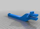
The third & final part is the support arm - this has to be printed diagonally across the build plate, otherwise it won't fit.
HolderMount.png
This is different to the other parts, it needs supports - temporary props to support the overhangs. The slicing programme automatically adds these - you can do it manually, but having no experience of this, I want to see how the programme does it. The supports can be easily ( ?! ) broken away when the print has finished.
So far all is going well. I've ordered some cork matting to put under the feet of the printer - it's on a cantilever computer desk, with a formica surface, and it does vibrate & jump around a bit. It's not that noisy, but running for long periods ( hours + ), it could be annoying. I can't hear it in my bedroom, with the door closed, so overnight printing is possible, I just have to have confidence it doesn't screw up the minute I close the door. I've also ordered spare belts & a nozzle, as I reckon these are the parts that could give out!
Dave
Dave
 

Dave Ward

Still Trying New Things
SMF Supporter
Joined
Apr 27, 2018
Messages
8,686
Points
113
Location
South Gloucestershire
First Name
David
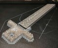
Support arm - about an hour into printing
DSCF4083.JPG
Very complicated! - the bits at the top - the straight bar - are the actual structure of the arm - the zig-zag bits are the print supports for the overhang.
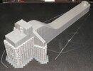
After 4 3/4 hours this is the final result, still on the build plate.
DSCF4084.JPG
I'll leave this until tomorrow, when I can find out how easy it is to break those supports off.
I think I'll experiment with a few small models, reducing the layer height & speed, to see what that does for quality.....................
Dave
 

Si Benson

SMF Supporter
Joined
Apr 27, 2018
Messages
3,327
Points
113
First Name
Si
I bet you where grinning like a Cheshire Cat when you got the nut to run down the thread….well done Dave :thumb2:
 

Tim Marlow

Little blokes aficionado
SMF Supporter
Joined
Apr 27, 2018
Messages
16,835
Points
113
Location
Somerset
First Name
Tim
Going great guns Dave. Layer lines look a little less pronounced on that one…..
 

Dave Ward

Still Trying New Things
SMF Supporter
Joined
Apr 27, 2018
Messages
8,686
Points
113
Location
South Gloucestershire
First Name
David
Going great guns Dave. Layer lines look a little less pronounced on that one…..
I think a new build plate & re-levelling it afterwards has helped!
The problem is that there are so many parameters you can vary, and it's difficult to know where to start - I've watched a lot of YouTube videos about improving quality, but 90% assume that you have prior knowledge ( which I don't ). The time taken for each print means that effects of changes to the parameters aren't quick to implement. There are several things that I haven't seen any answer for - like turning a model to point along the X-axis, or the Y, or diagonally across the build plate - does this have any effect on the print? I have absolutely no idea!!
Dave
 

Tim Marlow

Little blokes aficionado
SMF Supporter
Joined
Apr 27, 2018
Messages
16,835
Points
113
Location
Somerset
First Name
Tim
I think a new build plate & re-levelling it afterwards has helped!
The problem is that there are so many parameters you can vary, and it's difficult to know where to start - I've watched a lot of YouTube videos about improving quality, but 90% assume that you have prior knowledge ( which I don't ). The time taken for each print means that effects of changes to the parameters aren't quick to implement. There are several things that I haven't seen any answer for - like turning a model to point along the X-axis, or the Y, or diagonally across the build plate - does this have any effect on the print? I have absolutely no idea!!
Dave
Sounds a bit like airbrushing……you can read and watch what you like, but in the end you’ve just got to do it a lot to get the feel for it…..
 

Komedy

SMF Supporter
Joined
Jan 5, 2020
Messages
287
Points
63
First Name
Warren
Hi Dave

Coming along great guns. There are lots of downloadable calibration test prints that you can find to test and fine tune specific parameters. These are great as the print times are not to hefty, so you can print, tune and quickly get a comparison before moving on to the next

Warren
 

Gary MacKenzie

SMF Supporter
Joined
Apr 28, 2018
Messages
1,039
Points
113
Location
Forres, Scotland
First Name
Gary
I think a new build plate & re-levelling it afterwards has helped!
The problem is that there are so many parameters you can vary, and it's difficult to know where to start - I've watched a lot of YouTube videos about improving quality, but 90% assume that you have prior knowledge ( which I don't ). The time taken for each print means that effects of changes to the parameters aren't quick to implement. There are several things that I haven't seen any answer for - like turning a model to point along the X-axis, or the Y, or diagonally across the build plate - does this have any effect on the print? I have absolutely no idea!!
Dave
As it is FDM printing I would look at all the stuff done by Josef Prusa, he is a long-term filament printing guru/designer/entrepreneur.
Unclejessy uses both filament and resin and is usually very easy to follow.

Prusa , showing how he sets up and calibrates one of his printers, but the general info should help @


another possibly useful tuning video @


test of slicers and support settings @
 
Last edited:

adt70hk

I know its a bit sad but I like quickbuild kits!!!
SMF Supporter
Joined
Sep 4, 2019
Messages
9,517
Points
113
First Name
Andrew
Dave

That really has come a long way already. Very well done indeed. Can't wait to see what else you do!!

ATB.

Andrew
 

Neil Merryweather

SMF Supporter
Joined
Dec 29, 2018
Messages
4,444
Points
113
Location
London
First Name
Neil
the big issue with support in FDM printing is the support INTERFACE.
CURA has settings for this ,I don't know about your programme.
What you will be tweaking is the AIR GAP -ie the space between the top of the support and the model itself. it's frightfully hit and miss, I'm afraid, and probably different for every brand of FDM.
Good luck
N
 

Jim R

SMF Supporter
Joined
Apr 27, 2018
Messages
13,791
Points
113
Location
Shropshire
First Name
Jim
Well Dave this is certainly taking a lot of time, thought and study. I'm sure you'll get there in the end and it's keeping you out of the pub! Well maybe not - a few hours trying to juggle all the possible setting combinations could actually send you to the pub ;)
 

Dave Ward

Still Trying New Things
SMF Supporter
Joined
Apr 27, 2018
Messages
8,686
Points
113
Location
South Gloucestershire
First Name
David
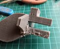
Ah Supports! I'd printed the spool support arm with the PrusaSlicer automatic generation of supports. I started trying to break them off. The PLA is tough stuff - I've removed a lot, but when I managed to break a scalpel blade I gave up for the day!!
DSCF4091.JPG
Whilst I was doing this I printed out a couple of small models
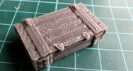
A wooden crate
DSCF4090.JPG
The resolution just isn't there, printing at its finest & slower speed. Still, prime it, paint it & it would do as part of a lorry load.
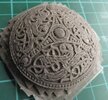
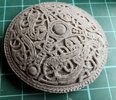
This took about 1 1/2 hours to print it's about 55 to 60mm in diameter - from Thingiverse, a Viking brooch by 'Prot0typ1cal'
DSCF4085.JPG
When the brim & supports cleaned up
DSCF4087.JPG
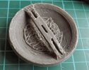
And the back more or less cleaned up of supports
DSCF4088.JPG
The layer height I was using was 0.08mm, but I think the limitation is due to the nozzle diameter of 0.4mm. You can get smaller nozzles, but this adds another complication of flow rates. You can see why cinematic props are made by FDM, prime it & paint it silver, then a fine black wash - at more than 3-4m, it'd pass as real! I'm beginning to see the lower end limits of FDM printing
Dave
 

langy71

SMF Supporter
Joined
Apr 27, 2018
Messages
1,563
Points
113
Location
Nottingham
First Name
Chris
Dave, can you not cut the supports away with a pair of sprue cutters / nippers? It might save you a fortune on scalpel blades..
 

Dave Ward

Still Trying New Things
SMF Supporter
Joined
Apr 27, 2018
Messages
8,686
Points
113
Location
South Gloucestershire
First Name
David
Dave, can you not cut the supports away with a pair of sprue cutters / nippers? It might save you a fortune on scalpel blades..
That's how I started off - I was using the scalpel to reach bits the sprue cutter couldn't - I've got out the big guns now - the Stanley Knife!
Dave
 

Neil Merryweather

SMF Supporter
Joined
Dec 29, 2018
Messages
4,444
Points
113
Location
London
First Name
Neil
Ah Supports! I'd printed the spool support arm with the PrusaSlicer automatic generation of supports. I started trying to break them off. The PLA is tough stuff - I've removed a lot, but when I managed to break a scalpel blade I gave up for the day!!
View attachment 472854
Whilst I was doing this I printed out a couple of small models
A wooden crate
View attachment 472853
The resolution just isn't there, printing at its finest & slower speed. Still, prime it, paint it & it would do as part of a lorry load.
This took about 1 1/2 hours to print it's about 55 to 60mm in diameter - from Thingiverse, a Viking brooch by 'Prot0typ1cal'
View attachment 472850
When the brim & supports cleaned up
View attachment 472851
And the back more or less cleaned up of supports
View attachment 472852
The layer height I was using was 0.08mm, but I think the limitation is due to the nozzle diameter of 0.4mm. You can get smaller nozzles, but this adds another complication of flow rates. You can see why cinematic props are made by FDM, prime it & paint it silver, then a fine black wash - at more than 3-4m, it'd pass as real! I'm beginning to see the lower end limits of FDM printing
Dave
Try building it on its edge, Dave. You might be surprised. A dome is generally self supporting, and if you put the brooch pin vertical you shouldn't need any at all. It will take longer,of course.
Generally speaking it's not the layer height that is restricted by the nozzle size, rather the detail definition.
0.4mm is not a problem on real life objects, but scale down to 1.35....

Yes we use them a lot in film prop making, but we still have to finish the parts to within an inch of their lives, because you can bet the director chooses to zoom right in on what you thought was for the background! :rolling: :tears-of-joy:
 

Neil Merryweather

SMF Supporter
Joined
Dec 29, 2018
Messages
4,444
Points
113
Location
London
First Name
Neil
That's what I meant by the support interface, you need enough to do the job but not so much that you ruin the piece whilst removing it. THAT'S the dark art part!
Stay focused, Grasshopper :tongue-out3:
 

Dave Ward

Still Trying New Things
SMF Supporter
Joined
Apr 27, 2018
Messages
8,686
Points
113
Location
South Gloucestershire
First Name
David
I printed out a few calibration models, then levelled the bed, sliced a new model with a few settings tweaked & it's about 3 hours into a 4 our print....................
I have put the printer on a cork mat ( from a model railway bits shop ), and it's much better
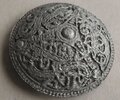
I primed yesterday's Viking brooch, painted silver, then a light wash of black............
DSCF4092.JPG
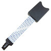
One thing that I have found a problem with, due to my fat fingers is, putting the micro-sd card into the mainboard. I've dropped the cards several times already, so I've ordered one of these
adaptor.jpg
The small end is permanently plugged into the mainboard, and you can use a standard SD card ( or micro with adapter ) at the other - the one I've ordered is 250mm long, so the free end should be able to be placed on the top of the printer, in full view, and easy access!
Dave
 

Dave Ward

Still Trying New Things
SMF Supporter
Joined
Apr 27, 2018
Messages
8,686
Points
113
Location
South Gloucestershire
First Name
David
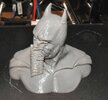
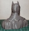
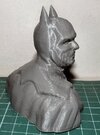
OK this is the Dark Knight from Thingiverse by MustangDave
DSCF4095.JPG
On the printer bed - a little bit of stringing between his ears, but nothing to worry about. I still haven't used the glue stick on this magnetic plate - the print stuck well.
DSCF4097.JPG
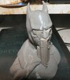
Looks more like Predator than Batman! The supports added hold up the chin. nose & brows.
Again, the supports are a real pig to remove and there's surface detail & texture lost
DSCF4099.JPG
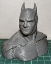
I'm really going to have to get this support business figured out - otherwise the bust is pretty good
DSCF4100.JPGDSCF4101.JPG

The tweaks I've applied to the settings seem to have worked, the layer lines are not apparent under normal light.
I'm going to have another go at this, paying extreme attention to the supports & make them as light as possible. I must also calibrate the Z-axis stepper motors- it may be that one side is slightly higher than the other. Of course this will mean re-levelling the build plate, but I'm getting the hang of that. I'm happy with progress so far, and I may venture into printing some of my own creations. They will be engineering orientated, the sculpting side of CAD modelling ( using Blender ) are a total unknown to me
Dave
 
Top