Jakko’s 1:35 Dragon Sd.Kfz. 251

JR

Member of the Rabble and Pyromania Consultant
SMF Supporter
Joined
May 26, 2015
Messages
17,282
Points
113
Location
lincs
First Name
John
This kit is not endearing itself to me.

View attachment 462772

That is the floor with the seat frames installed, but no seats yet because I want to paint underneath first. I cleaned up and glued those frames in place yesterday, and when I went on today, I discovered something rather important that the instructions make not clear at all:

View attachment 462773

Yes, for the wooden slat seats, you don’t need those frames at all … but that’s not how it looks from the drawings. They give me the impression that the wooden seats go on top of the frames just like the leather ones did.

View attachment 462774

So I duly cut them off again, and cleaned up the area after taking that photo. The instructions make another mistake about the wooden seats, namely that they show parts B12 and B13 without their legs, which go into the holes in the lockers under the seats. I had to trim down those legs, except the ones on the corners, because the other frames had filled the holes for them.

Also, those same parts don’t sit completely underneath the seats: instead, the seats sit inside the L-shape you can see in the top half of the wooden seats drawing. If you do glue B12/B13 fully under the seats, the rears will sit far too high and the inboard sides will be outboard of the locker edge — guess how I discovered all of this.

Those little parts also all come with a ton of ejector pin nodules that you have to remove, so these seats, of either type, are not a quick job at all. But this is them in place:

View attachment 462775

Still loose, because like I said, I want to paint underneath first.

Oh, yeah, and I filled the holes for the driver’s gas mask container on the left side of the firewall, as I doubt the French would have kept that in.
At this point I would have either set fire to it and turned it into a wreak or given up ! Hat off to you . As for those tracks :fearful::fearful::fearful::fearful:
 

Jakko

Way past the mad part
SMF Supporter
Joined
Apr 28, 2018
Messages
10,839
Points
113
First Name
Jakko
  • Haha
Reactions: JR

geegad

Can't cheat fate..
Joined
Mar 7, 2010
Messages
2,477
Points
113
First Name
John
Wow just gone through your thread amazing build great painting and weathering on this build...built this many many years ago and definitely not to this standard look forward to seeing more..and also like all the reference photos on your post
 

Jakko

Way past the mad part
SMF Supporter
Joined
Apr 28, 2018
Messages
10,839
Points
113
First Name
Jakko
...or Merkava ball&chains...
I think I’m lucky to have escaped those so far :smiling3:

Wow just gone through your thread amazing build great painting and weathering on this build...
Thanks :smiling3: Though I’ll dispute the great painting skills — there are plenty of people on here who are far better painters (and builders) than I am.

look forward to seeing more..and also like all the reference photos on your post
Well, let’s have some more, then :smiling3:

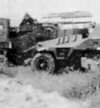
The cooling air exhaust louvres on the sides of the bonnet had me wondering how best to make them, not to mention what their sizes were. I began with the two known (to me, anyway) pictures of this vehicle, the one I already posted:

frans-in-indochina-1-jpg.462659


and one of even greater quality:

French Sd.Kfz. 251 in Indochina 2.jpg

and then scratchbuilt the louvres:

IMG_9129.JPG

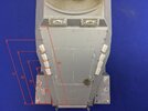
I opened the pictures of the real vehicle in Photoshop and used its measuring tool to get the length of the bonnet along its side edge as well as how far the front and rear of each exhaust louvre were from the front edge of the bonnet, and also did the same for the antenna mounting. That produced these dimensions:

IMG_9130.JPG

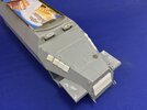
Each of the louvres is 5 mm × 5 mm large, the front two are 1 mm thick while the rear two are 1.5 mm, because it looks to me like the rear ones are slightly bigger in the photos. I made them wedge-shaped by taking a piece of plastic card of the right thickness, mark out a line 5 mm from the edge and then file an angle from the edge of the card to the line. Once that was done, I could cut out this wedge-shaped strip and chop it into 5 mm lengths. Then I rounded off the edges and glued the louvres to the model, with the filed side down — because I think the rear edge is at 90° to the outside, not to the armour plate.
 

Jakko

Way past the mad part
SMF Supporter
Joined
Apr 28, 2018
Messages
10,839
Points
113
First Name
Jakko
It’s just practice, really :smiling3:

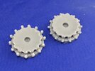
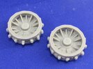
One of the last hurdles to tackle is the drive sprockets, which I’ve said before are missing the rollers and those rollers are in the wrong position. Looking more closely at pictures of the real thing, though, I came to the conclusion that it’s not the rollers that are placed wrong, but the flats on the rubber tyres. On the real thing, the positions of the rollers correspond to the spokes on the outer wheel half, and the model has it like that too. This must mean that the flats should be “advanced” around the rim a little …

That, though, seems almost impossible to do well, so I decided on another approach: file down the tyres to represent a worn one where the angles are mostly gone, and it’s nowhere near as obvious that the flats are in the wrong place.

While doing that, I also removed the teeth from the rear half of the wheel, then glued the halves together and started making the rollers. For that, I used 1.3 mm plastic rod, first cutting one to length by eye and adjusting it until it was the right size, and then making the other 27 to that length with my chopper tool.

However, they proved difficult to put in between the two halves, so after about five I pried them apart again (the glue was still soft) and stuck the rollers directly to the teeth I left on the front half instead. Here are the two front halves, one with and one without rollers:

9FA0C252-DD81-4D30-A90A-BA5BF86E5A51.jpeg

And complete with the back halves on too:

AAA2389D-186B-43C1-B62D-75760D8EA81D.jpeg
 

JR

Member of the Rabble and Pyromania Consultant
SMF Supporter
Joined
May 26, 2015
Messages
17,282
Points
113
Location
lincs
First Name
John
Scratchery at its best .
 

adt70hk

I know its a bit sad but I like quickbuild kits!!!
SMF Supporter
Joined
Sep 4, 2019
Messages
9,507
Points
113
First Name
Andrew
Just had a catch-up Jakko. Obviously pleased to hear your hand is on the mend and so your can get back to this.

That's coming on very nicely and is up to your usual high standard.

ATB.

Andrew
 

Jakko

Way past the mad part
SMF Supporter
Joined
Apr 28, 2018
Messages
10,839
Points
113
First Name
Jakko
I’m starting to agree with @John Race about those tracks …

33814A49-5AA2-4BD4-9760-1E00A922E721.jpeg

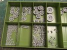
After finally cleaning up all the links, I started to assemble them into tracks. This entails hooking two links together and glueing a block over them to trap the pins and make the two links hinge. Unfortunately, due to the small size of about 8 by 5.5 mm for a link and 5 by 2.5 mm for a block (and probably my finger joints being stiffer than I would like), this is very hard to do. The blocks are difficult to pick up because of their size and shape, also difficult to put into position, especially with glue on, and it’s all too easy to get glue into the hinge by accident.

You can see a length of six links in the photo. That was made in two goes because both times, I got sick of it after three links … and I managed to glue one block to the next both times, so it only articulates in three places rather than five as it should.

After giving it some though, I tried hooking two links together with the block already in place, but that snaps off one of the pins so it’s not really a good method for making a working track, I think. Still, I’ve decided to glue the blocks to the links first and then see about adding them together. This is easier because you don’t have to handle a block and a length of track: put a block on your work surface, inside up, put glue on it and push a link down onto it. I’ll either try hooking the links together like I said, or I’ll stick most of the wheels onto the model and glue the tracks to them before painting, because articulation is irrelevant then.

My advice: buy another brand.
 

Jim R

SMF Supporter
Joined
Apr 27, 2018
Messages
13,754
Points
113
Location
Shropshire
First Name
Jim
Fraught with problems. Dragon have not done a good job with those tracks. The Trumpeter tracks on mine are much better thought out.
 

Tim Marlow

Little blokes aficionado
SMF Supporter
Joined
Apr 27, 2018
Messages
16,798
Points
113
Location
Somerset
First Name
Tim
I made some of this type up a few years ago for a 250. Hated them….far too fragile. Gave them an enamel wash to dirty them up and watched them fall apart again….at that point I took the second option below after the question…..

Question Jakko….do you really need them to articulate? If you do, then carry on :thumb2:
If not, then glue them together into link and length units and add the blocks afterwards…..it’s quite easy to make them removable when assembled.
 

Jakko

Way past the mad part
SMF Supporter
Joined
Apr 28, 2018
Messages
10,839
Points
113
First Name
Jakko
Fraught with problems. Dragon have not done a good job with those tracks. The Trumpeter tracks on mine are much better thought out.
The problem, really, is the size. On the Sd.Kfz. 7 I built earlier this year, the tracks are constructed in the same way, but because the links are a good deal larger, they’re far from as fiddly to hold and there’s more tolerance in the whole thing, so they went together much better.

I made some of this type up a few years ago for a 250. Hated them….far too fragile.
Those are slightly smaller, IIRC, but yeah … I can’t say I’m liking these.

Question Jakko….do you really need them to articulate? If you do, then carry on :thumb2:
I would like them to articulate to make installing and painting them easier, but I don’t absolutely need them to. It’s not like this is a motorised model :smiling3:

If not, then glue them together into link and length units and add the blocks afterwards…..it’s quite easy to make them removable when assembled.
I had been thinking about that too, but I would ideally want to keep the whole wheels and tracks off the model until after painting. I’m not sure I’ll be able to assemble the tracks fixed together in the right shape with the wheels still loose on the model, though. Perhaps some Blu-tack might come in handy to ensure the wheels stay on the model, though. I think I’ll try that.

just glue them up in sections.
If I do go this route, I think I’d prefer them as one piece rather than sections to be added after painting. But it might just be that it literally falls apart and I will have sections :smiling3:
 

JR

Member of the Rabble and Pyromania Consultant
SMF Supporter
Joined
May 26, 2015
Messages
17,282
Points
113
Location
lincs
First Name
John
Any thing as small as that causes nothing but stress, the mouldings are never deep or clean enough. I'd have gone for Fruils,. ok they are expensive but at the end of the day you want the model to be as good as possible.
 

Jakko

Way past the mad part
SMF Supporter
Joined
Apr 28, 2018
Messages
10,839
Points
113
First Name
Jakko
I’m getting these into shape, don’t worry ;) After the glue had dried on the ones on which I had glued the blocks, I could clip them together with some care and/or force, and only a small number of pins actually breaking. This leaves a track that hopefully bends enough to put it onto the model when it’s done, so I’ve by now glued a block to each of the links and need to wait for the glue to dry again before I can proceed. A dull job, but once you’ve found a method that works for you, it’s not that bad. Largely because you can clearly see the end after a while :smiling3:
 

Jakko

Way past the mad part
SMF Supporter
Joined
Apr 28, 2018
Messages
10,839
Points
113
First Name
Jakko
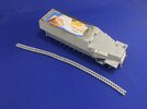
It works well enough that I finished one track today:

7B7C27A9-F9D4-4502-BB18-44E6FFF870AE.jpeg

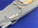
The rest of the model is also finished, thanks to the people over at Missing-Lynx, where I asked because I couldn’t work out what the support-like thing on the rear side of the bonnet is. From that question, it appears these are actually hatches for additional cooling as well. Since it’s not realistic to position it open, given there’s no interior to the engine bay and in any case, I had long glued the hull halves together, I just scribed the hatch outlines:

CD209BA3-876D-403B-9CD7-C7BAEAB6C499.jpeg

And with that, this model is almost ready for painting — just as soon as I build that other track, which is not easy on the thumbs :sad:
 
Top