Jakko’s Zvezda M4A2 Шерман, 1:35 scale

Jakko

Way past the mad part
SMF Supporter
Joined
Apr 28, 2018
Messages
10,821
Points
113
First Name
Jakko
In a way it is right up my street, but at the same time I kind of want to build this simply and fast … For which I should have bought an Asuka M4A2, it turns out :smiling3:

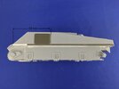
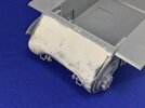
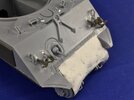
I added texture to the final drive housing:
A23E7E6D-ABDD-4D93-9F07-B1A60D3E64E7.jpeg

This is putty that I spread all over it with a spatula (working in small areas, not the whole thing at once), and while still wet I put liquid cement over it to thin it and added texture with a stiff brush. That turned out to be far too rough, so once dry I sanded it down to what I think (hope?) will be a quite acceptable texture after painting :smiling3:

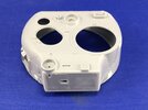
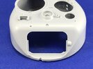
The turret has more problems than I thought. For starters, it has a strangely angular shape on its front face:
5AA0138B-09DB-4EF6-BBAD-F1BDFFB2B662.jpeg

Those sharp lines on either side of the front opening should not be there, and if you look closely you’ll see what almost amount to corners just above them, where the light catches, as well as a sharp line at the bottom of the curve between the sides and the roof. A bit of work with a file takes care of all of those:
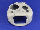
FDF204DD-DF80-43F4-9709-E33A1FD5E188.jpeg

At the rear, the corners are too sharp, so I filed those round as well:
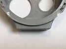
2249111D-BB47-40F4-9283-5F151C195337.jpeg83293DA4-1081-43E8-A171-448CBB7CE04C.jpeg

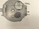
Harder to correct is that the loader’s hatch is wrong after all, it turned out over on Missing-Lynx. It’s slightly oversize, but I have no problem with that; what is an issue, is that its angle is very much off. Here is the angle the hatch on the model is set at:
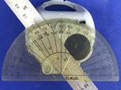
D29D3969-B24F-42C4-83F3-B0395AF1E1EA.jpeg

That should be 34 degrees, but I make it 53 … but I have a hard time finding a good way to correct this without it being a lot of work.
 

Jakko

Way past the mad part
SMF Supporter
Joined
Apr 28, 2018
Messages
10,821
Points
113
First Name
Jakko
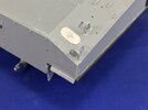
The Sherman had a compartment on each side at the rear corners of the hull, in which track grousers were stowed (metal bars that could be bolted to the tracks for better traction in soft ground). On the M4, M4A1 and M4A4, there was a little air scoop on top (with a bolt so it could be removed for access) to draw in cooling air over the fuel tanks, but the M4A2 and M4A3 didn’t need that, so they had a simple plate instead as a lid on the compartment. Now, Zvezda moulded those lids as rectangles with rounded corners:

5B5A9B9A-D57F-4638-AEB6-1F4769C8E40F.jpeg

However, on the real tank they had semicircular ends. I cut some thin plastic card to the right size (4.5 mm wide by 8.5 mm long) and cut and filed rounded ends to them. After cutting the moulded-on lids off, I glued the plates to the tank and added a punched bolt head to the centre:

0468C834-D3E2-43FD-81F4-E5248AAF23B6.jpeg

The engine deck, by the way, is mostly separate, except for the rearmost horizontal plate. You can pose the grilles open, but there is no interior detail to them and the engine bay is both completely empty and has internal bracings and things that aren’t on the real tank.
 

Jakko

Way past the mad part
SMF Supporter
Joined
Apr 28, 2018
Messages
10,821
Points
113
First Name
Jakko
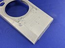
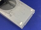
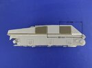
On the underside of the kit’s sponsons is a curious ridge that wasn’t there on the real tank, but which appears to serve as something to glue strips B5 and B6 to. Those are strips with holes that were welded to the real tank so that sand shields could be bolted to them, but Zvezda moulded the bolt holes wrong: they’re represented as large dimples in the middle of the strip, when they should be small holes just above the bottom edge. You could replace the parts by plastic strip and drill small holes in the correct places, but I used some Asuka parts instead (and cut away the ridge), as I had them spare from an M4A1 kit I built:

7504B1FD-B564-4DC1-863F-1F43FAEC0336.jpeg3682DA83-F562-4076-B7FA-EC0058911BB2.jpeg

Though I had to replace the short front section by plastic strip because the Asuka parts had a narrower bit there that isn’t correct for welded-hull Shermans. I still need to drill the holes in them, and also drill through the holes Asuka moulded into the strips for better appearance.

The armour plates on the sides are also Asuka parts, because they’re better than the ones Zvezda provides. I added measurements for their placement in the pictures, because the diagram in the instructions has those of the rectangular plates wrong.
 

Mini Me

SMF Supporter
Joined
Jun 1, 2018
Messages
10,160
Points
113
First Name
Rick
Hi Jakko, looking good so far.........if I understand you correctly, there is a 19 degree discrepancy in the loader hatch orientation? That is a HUGE error, I'm wondering if there is even room on the turret roof to orient it correctly.....that is without reducing the opening to the correct dimensions as well.....your thoughts?
Rick H.
 

Ian M

Administrator
Staff member
Administrator
Moderator
SMF Supporter
Joined
Dec 14, 2008
Messages
19,727
Points
113
Location
Falster, Denmark
First Name
Ian
This is a very interesting thread Jakko.
Regarding the loaders hatch angle, could you scribe and cut it out in a circle and turn the disc in situ thus change the angle. 34 to 53 is a big error, I thing someone twisted their figures when they measured it as 35. And noted 53 down.!
 

Mini Me

SMF Supporter
Joined
Jun 1, 2018
Messages
10,160
Points
113
First Name
Rick
I think you are on to something there Ian....a 1 degree difference would be nothing to worry over. A circle cutter perhaps...... with a hatch opening styrene plug to center it on.....certainly worth a try. Rick H.
 

Jakko

Way past the mad part
SMF Supporter
Joined
Apr 28, 2018
Messages
10,821
Points
113
First Name
Jakko
Still building out of the box then Jakko. It’s just that you’re using the spares box ;)
I hadn’t thought of it like that, but yeah, you’re right :smiling3:

Probably best you don't follow my out the box build of the tamiya m4a3 75mm when I get started ,you'll be horrified I'm sure lol.
Nah, I’ve built those out of the box too, I know what to expect with them :smiling3:

Neat work. As always you are raising this to another level of accuracy.
To be fair, the kit is generally OK but benefits from a little work to make it much better. Some of the detail is a little wrong but not badly so — I wouldn’t hesitate to recommend it to someone who just wants to build a Sherman and have it look right. The only major problem is the loader’s hatch.

if I understand you correctly, there is a 19 degree discrepancy in the loader hatch orientation?
Yes, it is really very far out of true. See below for more on this :smiling3:

I'm wondering if there is even room on the turret roof to orient it correctly.....that is without reducing the opening to the correct dimensions as well.....your thoughts?
I think there is, based on placing the hatch in its proper orientation, but I suspect that if you do that, it will end up underneath the .50-calibre machine-gun barrel stowage. If you look at the turret roof, there are two rectangular depressions moulded in, one between the two hatch openings and another in line with it at the rear. Into these will go clamps in which a barrel can be stowed, when the machine gun is removed from the commander’s hatch, and on the real tank, of course, that barrel sits between the hatches. I haven’t fully measured it out yet on the kit, but it looks like the edge of the hatch would end up under the barrel …

Regarding the loaders hatch angle, could you scribe and cut it out in a circle and turn the disc in situ thus change the angle.
It looks like the front of the hatch, just behind the round opening for the loader’s periscope, is in the right place, so the hatch will need to be rotated around that. It should be possible, if you’re skilled enough, to cut and file a new opening oriented like that, and fill in the back of the old one. However, I don’t think I’m up to that :smiling3:

What I think I’ll do instead is to glue the hatch into place, fill the seams, file and sand it all flat, and scribe a new hatch outline into the turret roof. I will then either have to scratchbuild the hatch springs and hinge, which is fairly straightforward, or try and cut them off neatly beforehand so I can just glue them on in the right spot.

34 to 53 is a big error, I thing someone twisted their figures when they measured it as 35. And noted 53 down.!
What I suspect to be going on is this:

1998542_56947e1ad0d7f313d9d97ebf5e0106c8_t.jpg

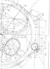
That’s a photograph of one of the drawings in the book Son of Sherman with the Zvezda hatch placed on top of the one in the drawing. The kit turret’s hatch opening is pretty much exactly the same size and is also angled as in the drawing, so I think Zvezda used this as the basis for their model. Compare to this original technical drawing:

3138414_47270ea0d21ab734d7c6672ad8701ab1.jpg (via Kurt Laughlin over on Missing-Lynx)

… and you can see clearly that the hatch is set at a very different angle than in the book. As the technical drawing also has the hatch opening’s dimensions, measuring up the kit part showed it to be slightly too large, but not enough that I would have cared about it. The angle just looks wrong, though, especially now that I know about it :smiling3:

Son of Sherman is a really good book to own if you’re interested in the details of Sherman tanks, but I learned from this that while its drawings illustrate the changing features of the tanks very well, they aren’t usable for building accurate models from.
 

Mini Me

SMF Supporter
Joined
Jun 1, 2018
Messages
10,160
Points
113
First Name
Rick
Looking at the Tech. dwg. indicates to me that the hatch opening is19 3/8", if your models hatch is longer than that, may be the reason for it colliding with the machine gun barrel brkt. Also I see that the dimensions are all ref'd. off the centerline of the turret's N/S E/W axis so you would need to check your model to see if all hatches brkts. hinge mounts etc. are in their proper places and go from there........how far are we down this "rabbit hole" ;)
 
Last edited:
  • Wow
Reactions: JR

Graeme C.

SMF Supporter
Joined
Apr 29, 2018
Messages
1,485
Points
113
First Name
Graeme
Very impressed with the research & modifications you've done Jakko, looking at the engineering drawing for the loaders hatch vs the book drawing there is a discrepancy. Having worked in engineering for 35 years (14 years in a tank factory!) I know how often drawings & designs are changed, is it possible that there's a difference between as originally drawn & as built?
 

Jakko

Way past the mad part
SMF Supporter
Joined
Apr 28, 2018
Messages
10,821
Points
113
First Name
Jakko
the Tech. dwg. indicates to me that the hatch opening is19 3/8", if your models hatch is longer than that, may be the reason for it colliding with the machine gun barrel brkt.
Yes, that is the problem: the hatch is just under a millimetre longer than it should be, and just over half a millimetre wider, off the top of my head. This is small enough that you wouldn’t see it unless there is something in the way, like that barrel.

Also I see that the dimensions are all ref'd. off the centerline of the turret's N/S E/W axis so you would need to check your model to see if all hatches brkts. hinge mounts etc. are in their proper places and go from there........how far are we down this "rabbit hole" ;)
Not that far :smiling3: If you’re the kind of modeller who wants all that kind of thing right to that extent, then the solution is simple: buy an Asuka kit of an M4A2, not a Zvezda one :smiling3: Of course, for the price of one Asuka Sherman you can buy two to two-and-a-half Zvezda Shermans …

Very impressed with the research
The research isn’t mine — you get that for free if you post about things like detailling Sherman models on a forum that the aforementioned Kurt Laughlin also frequents :smiling3:

is it possible that there's a difference between as originally drawn & as built?
I don’t think so, if you look closely at photos of Sherman turrets then it’s quickly clear that the kit is wrong and the technical drawing isn’t.
 

Mini Me

SMF Supporter
Joined
Jun 1, 2018
Messages
10,160
Points
113
First Name
Rick
Well Jakko, it's your call as to how deep you want to get into this kit.......you know what you are up against and I won't criticize you if you choose something less than "perfection" Have fun.... ;) Rick H.
 

rtfoe

SMF Supporter
Joined
Apr 29, 2018
Messages
7,511
Points
113
Location
Malaysia
First Name
Richard
I always say if it doesn't make you dizzy by just looking at it then it should be just fine. :smiling2: Or having a rivet counter ( I normally call these guys out who don't build but criticize) missing it completely distracted by the level of the other corrections and never knew about it.
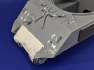
A missing hatch would have been a doozy though. :tears-of-joy:

Cheers,
Richard
 

Lee Drennen

Box Stock Builder with a Twist/ Rabble Member
SMF Supporter
Joined
Apr 29, 2018
Messages
5,653
Points
113
Location
Wortham Mo
First Name
Lee
Jakko Wow snuck this one under my radar. Very impressive build and a lot of informational history you have added very useful. I’ll try to keep up and thanks for joining us.
 

Jakko

Way past the mad part
SMF Supporter
Joined
Apr 28, 2018
Messages
10,821
Points
113
First Name
Jakko
Had a catch up, interesting to read about the details - yet another incredible build happening.
Thanks :smiling3: It’s really just some substitutions of kit parts for better ones from the spares box, though, if you ask me …

Well Jakko, it's your call as to how deep you want to get into this kit.......
I like models to be accurate, but at the same time I’m not fussed about things being slightly off as long as they don’t look wrong. How difficult it is to correct is also a major factor — take the armour plates on the sides, for example: Zvezda has their placement clearly wrong, but correcting that is just a matter of looking up the real locations (they’re found in several sources) and converting the measurements to 1:35 scale. Anyone who knows the way around a calculator and a ruler can get these right :smiling3: Some other things are harder to correct, of course, but like I said before: this kit is good enough for most purposes, and really, it gets more right than it gets wrong. It could have been a really good Sherman for a really good price if Zvezda had done their best just a little bit more.

I always say if it doesn't make you dizzy by just looking at it then it should be just fine. :smiling2:
That seems as good a philosophy as any, yes. That hatch makes me dizzy :smiling3:

Very impressive build and a lot of informational history you have added very useful.
Thanks :smiling3:
 

Jakko

Way past the mad part
SMF Supporter
Joined
Apr 28, 2018
Messages
10,821
Points
113
First Name
Jakko
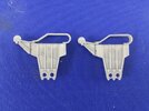
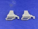
At the front, I filled the locating holes for the brush guards for the headlights and horn, because although the Zvezda parts aren’t bad, they’re overly thick.

C735A080-132A-417B-81E3-02AB3175B67E.jpeg

The best replacement for the brush guards would be thin metal, like from an etched set or scratchbuilt, but I don’t have any of the former nor the inclination to do the latter, so I went to Asuka again. Their kits almost invariably have both plastic parts and etched ones, so you will always have spares, and the plastic parts, though still a little thick due to moulding limitations, are much thinner than Zvezda’s:

0C3BFEC7-4D73-483F-AC3C-8F596ADFDFDD.jpeg

On the left-hand side of the tank, I also replaced Zvezda’s horn by one from Asuka, which again you often get spare if you build one of their Shermans because they tend to include multiple types. The reason is that Zvezda made a very basic mistake with theirs: rather than moulding slots into the front, they have put ridges on. Given the small size, this is just about impossible to correct, so replacing it is far simpler.

Note also that I removed the plastic strip sand shield attachments at the front, because it was pointed out to me that they should be tapered a little, not straight. Attempting to correct them, I cut through by accident, and rather than make new ones, I went back to looking through my Sherman spares box. In that, I found attachment strips for an M4A3 that I had overlooked the other day, so I just took the front strips from that and stuck them to the model.

You may have spotted the U-shaped groove between the hatches on the hull deck. This is a ventilator opening, and the kit provides a cover that fits over it. Early, large-hatch M4A2 tanks didn’t have that fitted, so the part is essentially optional if you’re building this kit. I also put in all four driver’s periscopes, because most kits (including the Asuka ones) generally mould the fixed ones in the hull as closed. Another good point about this kit is that the driver’s periscopes can be turned to face in any direction, another minor issue with the Asuka kits, which mould the rotating bases integrally with the hatches.

On the back, the tail lights are both good and bad at the same time. Zvezda moulds them as being attached by a little bent pipe (through which the electrical cable runs), which is how it should be. Most other manufacturers mould a little stalk onto the rear deck and have you glue the light to it instead. On the other side, the face of the light is very poor. However, as I don’t seem to have any Sherman tail lights, I have used the Zvezda part anyway:

7E7C36D7-FC8A-46EE-AD40-EBF3903C2EF9.jpeg

The brush guards at the rear are moulded thinner than the ones at the front, oddly enough, so I did use the kit parts here.
 
Last edited:

Jakko

Way past the mad part
SMF Supporter
Joined
Apr 28, 2018
Messages
10,821
Points
113
First Name
Jakko
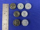
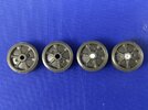
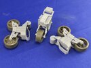
On to the suspension. Zvezda has made a couple of decisions here that make it awkward to get the bogies to look as good as they could. First there is the lack of detail in the wheels that I already mentioned, but here is a full comparison between the green Asuka wheels and the grey Zvezda ones:

1894CBD3-0983-417C-A285-5C6AA3469E93.jpeg

The grey wheel in the top row is Dragon, for another comparison in terms of detail. The dished wheels in the middle are not normally seen on Soviet M4A2 tanks with 75 mm guns, but were used on those with 76 mm guns (and thus, the later turret type) and I think also on some USMC 75 mm M4A2s in the Pacific, but don’t quote me on that :smiling3: There is no dished idler wheel, but that’s OK because those were only used after the war.

I will be using the Asuka wheels because of their better detail, but that gives the problem that the Asuka axle holes are larger than Zvezda’s, so some kind of bushing is needed to adapt them. I opted to drill out the wheels, inset plastic rod and then drill a hole for the Zvezda axles in that:

20C12CC9-E64A-44D6-BF6F-104AAE50AAC8.jpeg

The main reason for this slightly difficult method is that I didn’t have tube of a diameter that would fit both, or even one of the two, so drilling out the wheels for plastic rod that I did have, was the simplest solution in the end. You can do this without a lathe or any other fancy equipment: just a pin vice and two drills (one the size of the plastic rod, the other that of the kit axles) will do. The drill self-centres in the wheel holes, while drilling out the middle of plastic rod is also easy because it tends to centre in that as well — especially if there happens to be an air bubble, which is common in the thicker types of plastic rod.

The Asuka idler wheels need no adjustment: the holes in them are only slightly larger than the Zvezda axles, so they can go straight onto those.

Next, the skids on top of the bogies are overly thick, and really need to be thinned down for a better appearance. This is easy enough to do by carving, scraping and/or filing the inside edge of the skid on the outer bogie half; there is no need to bother with the inside, as it will be entirely out of sight. Compare what a difference this little job makes:

2A46C0FE-B868-455F-8A3E-8ECDEEB40849.jpegB7A4CFE9-329C-43E0-ADFF-37818CAC8BF2.jpeg

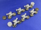
That done, I could assemble the bogies as per the instructions. This poses no problems at all, as the parts fit well. The main issue here is that the skid has been moulded integrally with both halves of the bogie body, meaning there is a big seam running all along its middle that has to be dealt with. Again, filing it down worked fine, even if the rounded front was a little tricky, and while I was doing that I also filed the front face of the bogie flat. There are four screw holes missing there too, which is not surprising since no manufacturer has yet moulded those as far as I know, so I marked them out with a template I made and drilled them out. I also added five bolt heads to the top of each bogie; there should be six, the the top rear inside one will be all but invisible, so I didn’t bother:

864EBC63-CFB0-4117-B6F6-A8621768962E.jpeg

The full suspension, then, including the Zvezda drive sprockets:

3329418D-6AF9-485E-BE91-E83F1EA181B3.jpeg

I used two spoked wheels on one of the bogies, because as mentioned I only had ten of the other wheels, and figuring that bogie damage would be somewhat common, I opted to have one bogie with different wheels.

Oh, yeah, before I forget: Zvezda tells you to paint the outside of the idler wheels (parts E15) and the return rollers (parts D2) with tyre colour. This is wrong: these wheels were completely made of steel and so were entirely painted in the basic vehicle colour. Only the roadwheels had rubber tyres.
 
Last edited:
Top