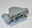
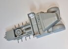
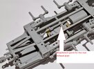
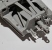
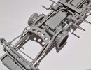
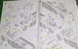
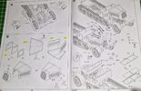
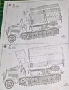
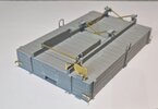
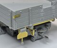
Los's 1/35 Trumpeter Sd.Kfz 7 KM m11

Jakko

Way past the mad part
SMF Supporter
Joined
Apr 28, 2018
Messages
10,979
Points
113
First Name
Jakko
FWIW, so does the photo from an original manual on page 68 of Die Halbkettenfahrzeuge des deutschen Heeres. But since this will all be invisible unless you’re building a diorama in which an inner wheel is being changed, does it really matter? :smiling3:
 

Panzerwrecker

SMF Supporter
Joined
Mar 2, 2022
Messages
362
Points
93
First Name
Los
FWIW, so does the photo from an original manual on page 68 of Die Halbkettenfahrzeuge des deutschen Heeres. But since this will all be invisible unless you’re building a diorama in which an inner wheel is being changed, does it really matter? :smiling3:
As you say, if not exposing the axle, then not one-bit TBH. It is interesting how different manufacturers manage to produce such different end results. All these museum resto vehicles really do muddy the waters somewhat.


One thing reading through the PT book on the 8T that I hadn't noticed before in period images, and no kit manufacturer has released to date, is: the first incarnation of the wooden bed (Holzpritsche) was attached to the original metalwork cab which had the cut off HL rounded track fenders. This was installed by the manufacturer Saurer in November 1943.

I notice both these images below show the late and reduced depth track fender. Dragon released the HL version with these fenders in kit#6794

That is a kit bash that I might attempt in the future

20220926_135509_resized.jpg20220926_135527_resized.jpg
 
Last edited:

JR

Member of the Rabble and Pyromania Consultant
SMF Supporter
Joined
May 26, 2015
Messages
17,393
Points
113
Location
lincs
First Name
John
Just noticed I have mounted the external cable guide bracket on the rear panel upside down:rolling: What a numptie:upside:
Can't believe you make mistakes, must be the the instructions Los .

Congratulations on a most detailed thread and high quality photos .It's more like a technical publication.
 

Panzerwrecker

SMF Supporter
Joined
Mar 2, 2022
Messages
362
Points
93
First Name
Los
Modifications and updates to the mittlerer Zugkraftwagen 8T (Sd.Kfz.7) Holzpritsche

As we are yet to start on the bodywork and cargo bed, I thought it may be worthwhile at this point to mention the various modifications that occurred during its short production run. Most changes were features that were dropped due to the materials savings plan.

First up as regards to manufacturers, the HL reference refers to vehicles manufactured under licence by Borgward and KM by Krauss Maffei

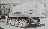
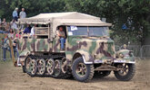
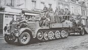
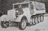
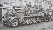
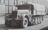
The first wooden cargo bodies (Holzpritsche) built on the m11 design were installed by the manufacturer Saurer as early as November 1943. These were first attached to the 1943 Typ HL m11 which retained the old-style metal driver’s compartment. At about the same time the assembly firm emblems were dropped from the radiator housing, as were the turn signals, side light and brake light. The headlights were also reduced in size and a pair of steel pins were welded to the front of the frame either side of the towing point to allow mounting of an external starter. The track guards were also reduced in depth.

Early cab with a reduced depth track guard and large headlights
20220926_135509_resized.jpg

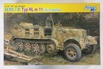
Dragon released a version in 2014 which they labelled a ‘Typ HL M11 1943 production’ in kit #6794 which had reduced depth track guards on the box art. Unfortunately, the kit only provided existing body floor mouldings with the older type of track guard and expected the modeller to reduce them by slicing them along their full length:surprised: This without any template or guide marks!
index.jpg


In 1944 the driver’s compartment was re-designed into the final, larger but simplified wooden cab version with a new instrument panel and angled track guards. The open glass panel in the windscreen was dropped and at least three variations in the design of the wooden side panels of the driver’s compartment existed. These being a rounded front, a second with a short straight bevel and a third with a long bevel. Krauss-Maffei were unable to start there Holtzpritsche production until Feb 1944 of which, by then, they would have likely been with the new cab layout.

Other modifications that are not so visibly obvious included the discontinuation of the inertia starter in 1944, The guide to access this and the cover plate were eliminated from the right front mudguard in early 1944. The final lightweight track plates were also introduced later that year.

The only changes to the cargo body were that the rifle racks were mounted to the equipment rack rather than to the floor. This meant that the Holzpritsche could be converted to a flatbed cargo vehicle simply by removing the seats and equipment rack.

Factory fresh. This has the large headlights, rounded cab panel profile and steel pins for an external starter. There is no assembly firm emblem visible on the radiator housing.
20220926_135715_resized.jpg

20220926_135754_resized.jpg

As for the issues and errors with this kit, there are many, but thankfully nothing that spoils it sufficiently to require a huge amount of extra work. Dimensionally the kit is a smidgen long compared to the drawings and the profile of the front fenders is slightly out. Neither warrants the amount of work required to correct IMO.

The kit only provides the larger headlights and has the access cover plate for the inertia starter on the right front mudguard. Both are easy to deal with if you wish to show a later build. Kubelwagen sized headlights being a good replacement. The kit does not provide the steel pins for the external starter either side of the front towing point so you might wish to add these. There is no driver's sun visor on the windscreen in the box either!

As already mentioned in step 16, the cab seat bench metalwork, and the seat cushion size and layout are incorrect. If it is important to you, these will need to be modified. The assembly firm emblem on the radiator housing is easy enough to remove should you wish and the three prominent rivets at the bottom of each fender should not have a bolt head on each. These look like a restoration anomaly so simply remove the bolt detail.

As for the cargo bed, there are a few errors and omissions here too. The PT drawings and period images show a cut out at the top of the rear tailgate. This was to accommodate items being towed and the kit part does not include this. It doesn't provide the steps on the interior of the same part either! Both these should be easy enough to correct. Later models had the rifle racks located onto the equipment rack. Trumpeter have a strange photo etch frame (part) PE-WB15 attached to the top clasps which are not shown in either PT drawings or period images. Maybe best to leave these off? The lower rifle butt locating rings are moulded to the floor on the kit. Later variants moved these to the equipment rack. As far as I can make out, they look to have been re-located to the top of the bottom plank.

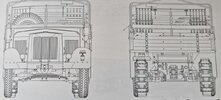
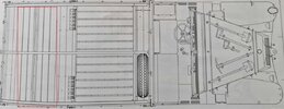
No assembly firm emblem, pins for the external starter, small headlights, windscreen sun visor, and the tailgate cut out and steps can all be seen in these drawings. It also shows the lightweight track design introduced at the end of 1944.
20220927_102631_resized.jpg

The equipment rack was attached the cargo floor by locating bars which fitted into sockets in the floor. They were, as the seat was, locked in place by blocks attached to the inside of the folding sides. The kit does not provide either of these. The bars would not be visible if fitted but the blocks would be. Again, a simple process to scratch from plastic card. Likewise, the sockets in the floor are not shown on the kit part and would be visible if you built a flatbed cargo version.

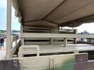
Strangely the cargo seats provided are engineered to sit opposite each other where in fact it sat across the width of the whole bed with seats facing back-to-back. There are also twin planked wooden seat back looking frames attached to each folding side. I’m pretty sure this is where Trumpeter researchers misinterpreted these as the seats and include a two benches positioned each side. Who knows?

The actual bench sits accross the bed (inside the red rectangle)
20220927_1026w35_resized.jpg

Lastly, the kit's instructions have you place the spare wheel (without any means of securing it) on the flat panel at the rear of the chassis when it should sit in the tools compartment in front of the equipment rack.

Scale drawings of both the equipment rack and cargo seat layout can be found in Panzer Tracts No 22-4 if you wish to scratch build them.

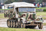
The Crompton collection 8T. You can see the rear bench seat layout clearly in these pics
bkayqy43e7hi8hwvp5ps.jpg3773904923_e9db17c45c_b.jpg

Tankfest Vehicle park (49).jpg


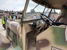
Nice pic of the cab instrument panel layout
Tankfest Vehicle park (48).jpg
 
Last edited:

Tim Marlow

Little blokes aficionado
SMF Supporter
Joined
Apr 27, 2018
Messages
16,909
Points
113
Location
Somerset
First Name
Tim
Excellent research and images Los. Looking forward to what you do with the model.
 

Panzerwrecker

SMF Supporter
Joined
Mar 2, 2022
Messages
362
Points
93
First Name
Los
I’m not a big fan of repetitive work so I like to spread the task of wheel and track clean up over a few sessions so this work continues at a glacial pace and is still ongoing.

The sprocket has three big issues. The main one is simple to remedy, if not a little fiddly and time consuming. Trumpeter have not offset the rollers so when you attach the tracks to the sprocket, they don’t sit flat against the track pads. The well published fix can be found here: https://www.perthmilitarymodelling.com/reviews/vehicles/trumpeter/tr01523d04.htm

The second is that the kit sprockets have bevelled grooves on the face. These don’t show in the Panzer Tracts book or appear in any reference image. TBH don’t even appear in the instruction drawings or Trumpeters own paint guide! These will require careful filling. The third problem is with the Photo-Etch step ring part (PE-WA1) It is too short to complete a full circle unless you narrow the circumference of the plastic inner ring it attaches to! It is beneficial to anneal it, or it will be difficult to bend, and the carpet monster will get a metallic snack!

A far easier solution to solve all the kit’s sprocket issue in one hit, is to use the Dragon sprockets or, go 3D printed. If you are lucky enough to own or know somebody with a 3D printer, there are 3D files available to download that offer some finely detailed sprockets. Simples!

At present I am still searching for a decent 3D printed set.

I’m not a big fan of rubber tyres on kits. I know they are mini replicas of the real thing so why should I be complaining? Although the kit ones are OK, the pattern is an authentic one etc, they just don’t take weathering products well. They also exhibit an unnatural shine that would need toning down in this scale. My option was to use Quick Wheel resin wheels. Whilst their wheel spokes are a little ‘off’ in terms of shape, the size and wheel tread pattern is authentic. I’m not sure these are as easily available in the UK as they once were. There are, however, many other manufacturers of these wheels in 1/35 nowadays. They include Def Model, Panzerart and ET Model to name a few.

The tracks are a three-piece affair. Nice if you want to model a burnt-out vehicle as the pads are a separate part. Apart from the tedious clean-up they look good and link together well. Use a thicker glue in construction to avoid sticking links together and you have a nice strong set of articulating tracks.

So, with work on steps 13 to 15 still ongoing let’s come back to these and move on to the bodybuilding steps

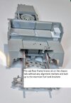
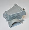
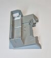
With some appreciated help from Jakko to correct the cab inaccuracies, I have reworked both the seat layout and the battery box. Its not 100% accurate but it's a step in the right direction. All the cab parts fit together precisely but it is worth test fitting your spacing on the chassis frame brace (parts WA1 & WA2) underneath the cab before they completely cure. Both these floor brace parts lines up on top of the chassis legs without any alignment tabs and butt up to the rear fuel tank brackets.

20221004_00346q36.jpg

Step 17 has you fit both the front fender body moulding part (WA4) and the cab assembly to the chassis. Fit the fender moulding first as it has a precise fit by way of a groove in the chassis legs and will confirm the spacing. The cab assembly floor braces at the rear just sit up against the rear fuel tank brackets but don’t sit on the chassis legs.

Having built a few of these I now find it much easier to build the bodywork into sub-assemblies off the chassis until I get some paint on. If you follow the instructions there is no way you can get paint into areas under the cab so I usually paint the fuel tank seperately. Sometimes just a dark shadow coat over the primer onto the top of the gearbox and all the areas under the cab will do.

I like to keep the front fender moulding, bulkhead and engine panels as one sub-assembly and the cab floor assembly as another.

20221004_003523.jpg

20221004_003136.jpg

To build it up like this you must keep the steering wheel shaft separate. As it is connected by way of photo-etch bracing to the inside of the bulkhead, attaching it to the bracing must be added before adding the instrument panel. This is impossible to do if it you add the steering shaft to the chassis as the instrument panel covers the connection point. The only fiddly aspect to this method of construction is you must connect the steering linkages to the steering box at the bottom of the steering shaft after connecting the bodywork to the chassis. There are two ways of achieving this. One is to simply snip off the pin on the bottom of the steering box, so your linkages just sit against them. This connection is hidden behind the fender so it's not a big issue. The second option, if you must keep the linkage and steering box connected is to push fit linkage part D50 onto the steering box at the bottom of the shaft before adding the whole front assembly to the chassis. This way the connection point to linkage part D6 is much more accessible under the fender arch.

20221004_003541.jpg

This method of construction keeps all the panels nice and tight. Assembling it in this manner means you can also add a painted engine to a painted chassis before adding the painted bodywork and be sure everything still lines up;)

20221004_003734.jpg
 
Last edited:

Panzerwrecker

SMF Supporter
Joined
Mar 2, 2022
Messages
362
Points
93
First Name
Los
So not a kit for someone new to modelling, is what you’re saying? ;)
LOL. No I would not recommend this particular kit, no. In fact I wouldn't include any halftrack on a 'first kit' list. Way too complicated. Put them off modelling for life :smiling5:

You definitely have to plan ahead with this one then. Looks really good so far
Yea Mick, it’s possible to do OK following the instructions religiously but I'd wager you would come a cropper somewhere along the line. probably a few times TBH:smiling2:
 

Jakko

Way past the mad part
SMF Supporter
Joined
Apr 28, 2018
Messages
10,979
Points
113
First Name
Jakko
LOL. No I would not recommend this particular kit, no. In fact I wouldn't include any halftrack on a 'first kit' list. Way too complicated. Put them off modelling for life :smiling5:
Or, for that matter, most Trumpeter kits in the first place. Too many bits that don’t fit overly well and need some work to get them in place at all.
 

JR

Member of the Rabble and Pyromania Consultant
SMF Supporter
Joined
May 26, 2015
Messages
17,393
Points
113
Location
lincs
First Name
John
Great photos once again Los.
 

Panzerwrecker

SMF Supporter
Joined
Mar 2, 2022
Messages
362
Points
93
First Name
Los
Continuing where we left off in step 17 we also have the exhaust pipe fitment which comes in two parts. They are fiddly to thread through the various holes and apertures in the frame. Fortunately, the join is engineered to hide inside the exhaust box. I would recommend adding the rear section first to get the correct spacing. Although not pointed out in the illustration, there is a small hole in the pipe just behind the box and this aligns with a pip on the tube underneath the winch.

20221006_2002711.jpg

Rear pipe exiting the rear panel
20221006_200723.jpg

The front section fits up through a hole in the front fender moulding and attaches to the manifold. It is a tight fit next to all the steering linkages. I won’t be fitting my front piece until after the front sub-assembly is fitted to the chassis.

Front pipework route.
20221006_200804.jpg

Step 18 is where you attach the engine bulkhead to the cab assembly. As already mentioned in an earlier post I’m not a fan of the assembly sequence so devised my own method of construction between the main body sub-assemblies in steps 17 through 19

If the instructions are followed to the letter in these stages, it is all too easy to misalign panels. Adding the bulkhead to the cab floor effectively ‘traps’ the steering shaft. The final placement of the bulkhead determines the position of the cab front panel (part WD18 in step 19), which in turn determines the spacing of the bonnet/hood and engine side panels against the radiator housing. Those triangular reinforcing brace mouldings can mess up a good fitment if they are not in exactly the right position on the bulkhead. It is from step 17 where it is most definitely worth cleaning up all the engine panel parts in step 21 and test fitting them for optimum fit.

Step 18 is also where you begin to add all the photo-etch steps which connect both the front sub-assembly and the cab sub-assembly. In my build this means adding all these steps at a later stage.

20221006_200941.jpg

If you have at this point kept the engine separate for painting, bear in mind that it will not fit in the bay once both the bulkhead (part WD12) and radiator housing (A27) are added.

Moving on to step 19, here we add all manner of cab and engine parts. The front cab panel with the instrument panel is also added. Trumpeter have bestowed us with a full complement of dial decals. Which is nice:hugging-face:

Step 20 just adds the front fender lower reinforcing braces which are provided on the photo-etch fret and step 21 builds up the radiator, engine sides and bonnet/hood.

Steps 22 and 23 finish off the cab and adds all the small accessories like lights, width indicators and tools. Trumpeter have provided a thin clear plastic screen to sit in the windscreen frame. The screen will hinge with care, but it is only by way of photo-etch hinges so won’t stand up to continuous movement.

20221006_200951.jpg


Building the load bed Steps 24 to 28

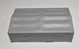
Whilst I’m still deflecting from finishing the tracks, I started pulling the cargo bed parts of the sprues and remembered how exaggerated the woodgrain is. A much larger issue is that this kit does not have the equipment rack included. It has some strange planking dividers instead. If you want to show a rack you will have to scratch build one or use the dragon kit part.

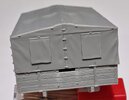
You have two options to display the cargo area. One is open with just the frame and one to use the provided tilt canvas cover. There is also a cover for the cab.

20221006_203928.jpg

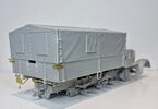
You can hide the fact that no equipment rack is present by simply adding the included tilt canvas moulding. The moulding of the canvas doesn’t look particularly exciting in bare plastic, and it is way too uniform and straight at the bottom edge. Unfortunately, the tilt frame is moulded inside the canvas, so you do not have the option to add it over the open build framework.

20221006_200148.jpg

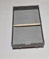
All the wooden panels are fee from sink marks on both sides which is a commendable achievement and the floor panel part WC23 is almost free from any apart from some shallow ones which are almost hidden under the support framework. The two main framework rails benefit from reducing the size of their locating nubs as they won’t sit flush otherwise. The panels that make up the sides all fit together well although, just like the frame rails, it is worth reducing the size of their locating nubs to get a nice flush fit on the bed.

Spacing stick used to keep a bendy side panel in line.
20221006_201847.jpg

20221006_200053.jpg

The instructions have you snip off the tops of all the upper hinge plates if you are fitting the tilt. This is a simplified answer and TBH the canvas would bulge over them. With the bottom edge all-round the tilt being too straight and uniform I will do some extra work on mine so whole hinge plates can be added. I also added a ‘towing option’ cut out in the rear panel along with two reinforcing strips as you see these a lot in period images.

20221006_200303.jpg

If you are not at all bothered about the kit’s inaccuracies in the load bed and follow the build steps it does all build up nicely. The inclusion of photo-etch for the reinforcing bars, clasps, number place and locking bar detail being particular nice touches.

20221006_224239.jpg

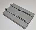
There should be a photo-etch trangular loadbed stop frame at the end of both chassis legs but for some reason the kit only provides the one:rolling:
20221006_224930.jpg

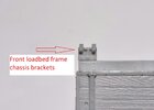
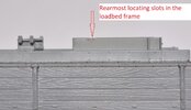
It very much looks like Trumpeter use the same chassis leg mouldings for all their Sd.Kf 7 variants with the locating tabs moulded in to accommodate all of them. What this means with this kit is that only the front and rear locating tabs are utilised. The front ones need almost entirely removing to make the bed frame brackets slot into them! The rearmost connection is precise but at the front it is anything but! TBH you can remove the front locating tabs altogether as the framework bracket detail ‘wraps’ around the chassis rails to align anyway.

20221006_2000q37.jpg20221006_2s00024.jpg


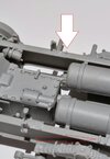
The bottom arrow points towards the location tabs positioned along the chassis legs and the white arrow is how small you need to reduce the front tabs to accept the front chassis frame brackets.
20221006_19593q4.jpg

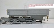
To make things even more frustrating the cargo bed on this variant connects to the chassis with a third middle bracket. This happens to sit just behind the shackle pin location point and in exactly the spot where the instruction diagram illustrates you orientate them! These can rotate fore or aft on the location hole in the chassis but, many would have already committed the glue. Add your own expletive!

20221006_2249510.jpg

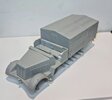
Test fit progress so far

20221006_230454.jpg20221006_230539.jpg
 
Last edited:

JR

Member of the Rabble and Pyromania Consultant
SMF Supporter
Joined
May 26, 2015
Messages
17,393
Points
113
Location
lincs
First Name
John
A highly commendable post Los, you cover the assembly so well in photos and text .
Far too hard for me to even think about attempting to build !
 
Top